
These Instructions cover all of our current Subaru – VW Bell Housing Kits:
The bell housing kit instructions below are in ‘Haynes Manual’ format, where the image numbers match the relevant paragraphs in the instructions. The paragraph numbers in blue are the ones which have corresponding photos in the sliding galleries.
If you think you know how to install your bell housing kit without reading the instructions or by just looking at the photos, don’t be surprised if / when you make mistakes, or have parts left when you think you have finished.
Clean your VW gearbox, at least all around the bell housing joint 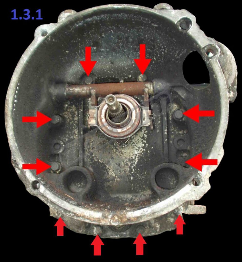
Remove the 10 bell housing bolts / nuts 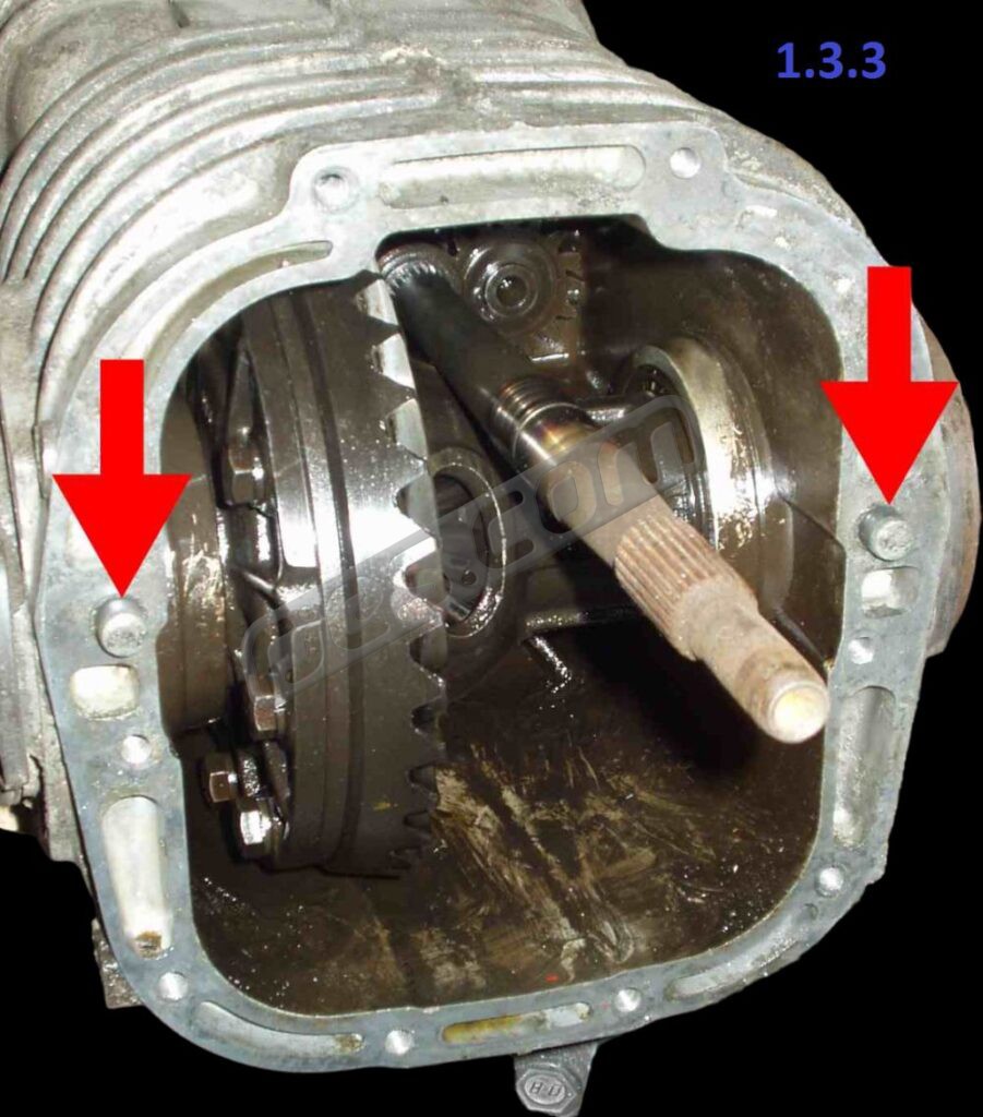
Bell housing alignment dowels 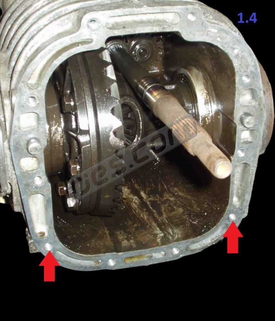
If your gearbox has bell housing studs / nuts rather then bolts, remove these two studs 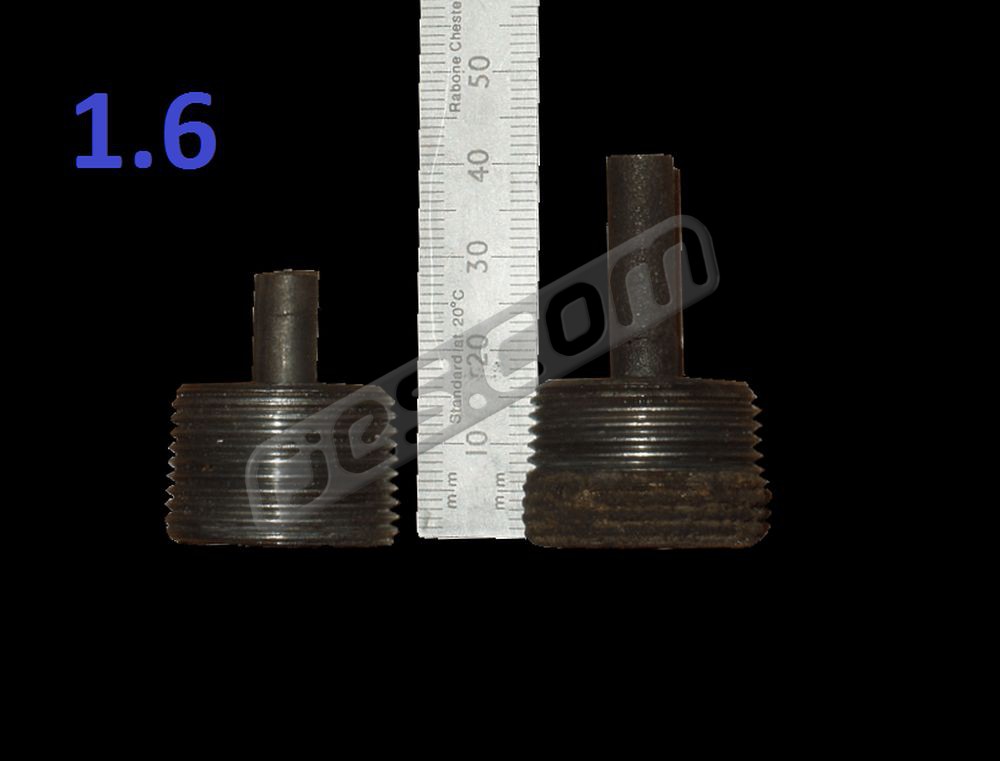
Shorten the drain plug magnet, or swap it for a Beetle drain plug 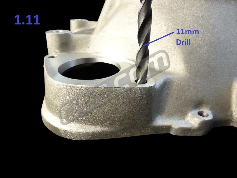
Drill the thread out of the lower starter hole (11mm drill) if you are using a bolt through to the engine tapping (‘Phase II’) 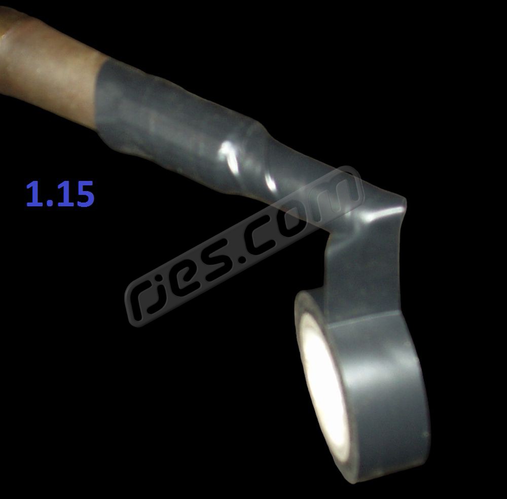
Tape over the unput shaft splines with PVC (insulation) tape in a spral, from the spline to the tip pf the shaft
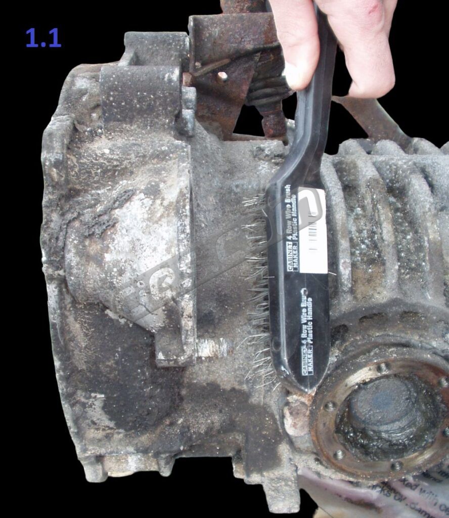
1.1 Clean your transaxle casing, especially around the bell housing joint. A wire brush then a solvent type degreaser works well.
1.2 Drain the oil from your transaxle if you haven’t already. Use a 17mm Allen key, or drain plug tool. No need to replace the drain plug.
1.3 Remove the bell housing from your VW transaxle.
1.3.1 The bell housing is retained by ten M8 bolts or nuts and studs – six inside the bell housing, and four below. Remove these.
1.3.2 Tap the bell housing lightly with a mallet (or hammer and block of wood) away from the transaxle to break the gasket joint. There will still be some oil in the diff housing. Slide the bell housing off the input shaft.
1.3.3 The bell housing is aligned with the diff housing with two 12mm dowels. They usually stay in the transaxle casing when the bell housing is removed. If yours come out with the bell housing, tap them out from other side with a drift, and refit then into the holes in the transaxle casing.
1.4 If your bell housing is fitted with studs and nuts rather than bolts, remove the highest two below the bell housing (they’re roughly at 4 o’clock and 8 o’clock, slightly above the oil drain plug). They will be replaced with longer bolts.
1.5 Carefully remove all traces of the original gasket from the transaxle casing. The casting is very soft magnesium and scratches very easily. Be careful not to scratch it. Pay particular attention around the two dowels (and all the studs if your bellhousing is mounted with studs not bolts), making sure no bits of gasket are left in the corners.
1.6 Your oil drain plug will have a long cylindrical magnet on the back. This will either need shortening or needs replacing with the Beetle equivalent (113 301 141 B) which already has a short magnet. Shorten it by 13mm with a grinder – the magnet is far too hard to be sawn. Clean all debris from the plug and magnet. Pay particular attention to the threads – they are often full of corroded magnesium. Fit the VW drain plug into the new bell housing, and tighten to 19 Nm (14 ft lb). Check to make sure the magnet does not come within 2mm of the machined bell housing face.
1.7 Tilt the transaxle slightly so the input shaft end is at the top. This prevents oil running out.
1.8 No longer applicable, please ignore
1.9 Clean the gasket face of the transaxle, and the input shaft from the end to back behind the ground section that the oil seal runs on with solvent degreaser.
1.10 No longer applicable, please ignore
1.11 If you are using a Phase II EJ series engine or an EZ or FA series, these all have the extra engine to gearbox bolts which Subaru added when superseding the Phase I EJ series and EG33 engines. The two lower studs, plus the two original upper bolts and extra bolts. One of the additional bolts replaces the Phase I stud screwed into the bell housing as the lower starter fastener with a bolt screwed into the engine, passing straight through the bell housing like the upper starter fastener.
To make the same bell housing kits suit the 4, 8 and 9 fastener bell housing bolt patterns we drill and tap the lower starter hole and supply a stud for use on the Phase I EJ and EG series engines. If you are using a Phase II EJ series, EZ or FA series engine you can either use the stud like a Phase I EJ series, or drill the hole out so the Subaru bolt can pass straight through and screw into the engine. If you go for the latter, drill the hole out to 11mm.
1.12 The holes at each end of the input shaft bore are taped over to keep dirt out of the seal. Remove the tape which covers the input shaft hole in the bell housing just before you install it. The oil seal is already installed in your new bell housing. The seal is pre-greased, so it will not run dry on first start up. Be careful to make sure no dirt gets in between removing the tape and finally fitting the bell housing too. DO NOT slide the bell housing over the input shaft yet (for a trial fit, etc).
1.13 No longer applicable, please ignore
1.14 Clean the face of the new bell housing which closes off the transaxle casing with solvent degreaser. Clean all the bits which will end up inside the bell housing, not just the machined face.
1.15 Wrap the input shaft with PVC insulating tape so the splines are just covered, right to the end. Start at the splines and wrap in a spiral towards the end, as this will make removing the tape easy later.
1.16 Apply gasket compound to the sealing face of the bell housing, and also the diff housing if required – follow the instructions on your gasket compound.
1.17 Slide the bell housing onto the input shaft, and start it on the two 12mm dowels. It should start on the dowels easily, but probably won’t push all the way on. This doesn’t matter as the bolts will pull it up
1.18 Loosely fit eight of the ten original VW bell housing bolts or nuts. Turn them by hand – not with power tools. The magnesium threads are easily damaged and difficult to repair. Miss out the two just above the oil drain plug (at about 4 o’clock and 8 o’clock), and fit the M8 x 60 cap screws from the kit with washers in their place.
1.19 Tighten all ten bolts / nuts with a torque wrench to 19 Nm (14 ft lb).
1.20 Remove the insulation tape from the input shaft.
Continue to:
- 2 for naturally aspirated ‘push to release’ clutch bell housing kits
- 3 for turbo ‘pull to release’ clutch bell housing kits
- 4 for MY05 –> low power turbo (<250 bhp) ‘push to release’ clutch bell housing kits
Remove the clutch release shaft arm circlip 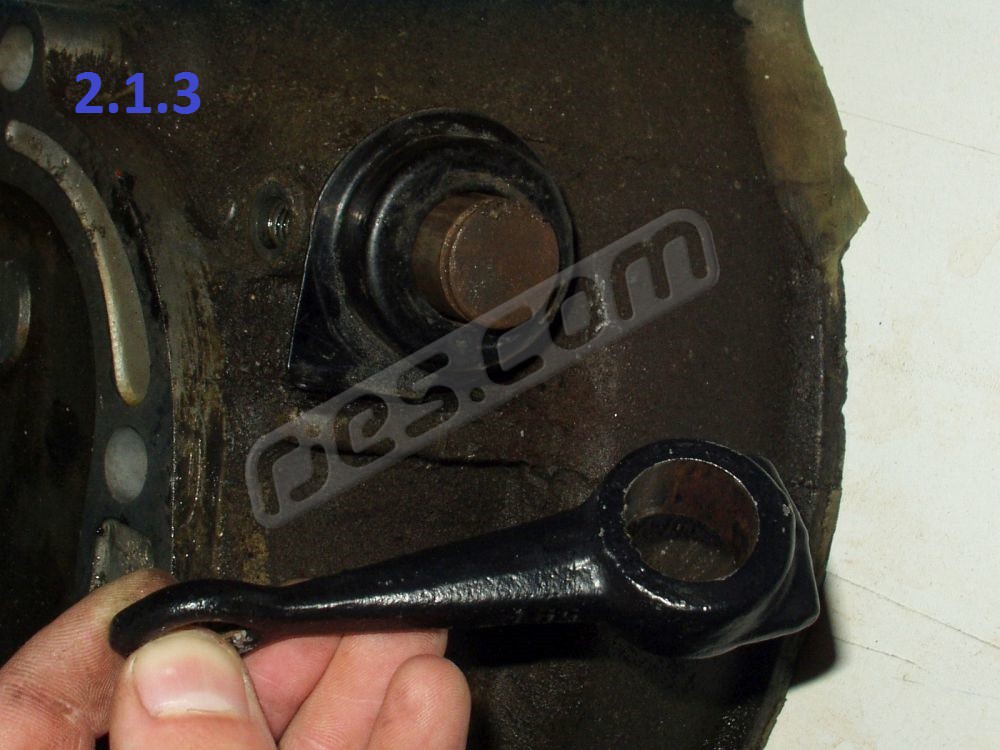
Remove the clutch release shaft arm 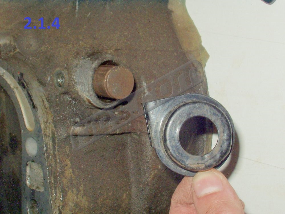
Remove the return spring and spring seat (if cable clutch) 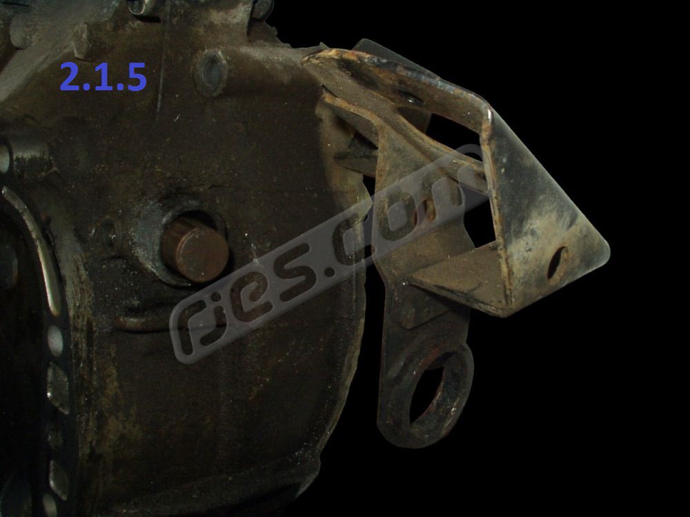
Remove the slave cylinder bracket (if hydraulic clutch) 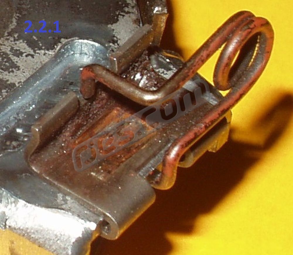
VW release bearing clips (badly worn as shown) 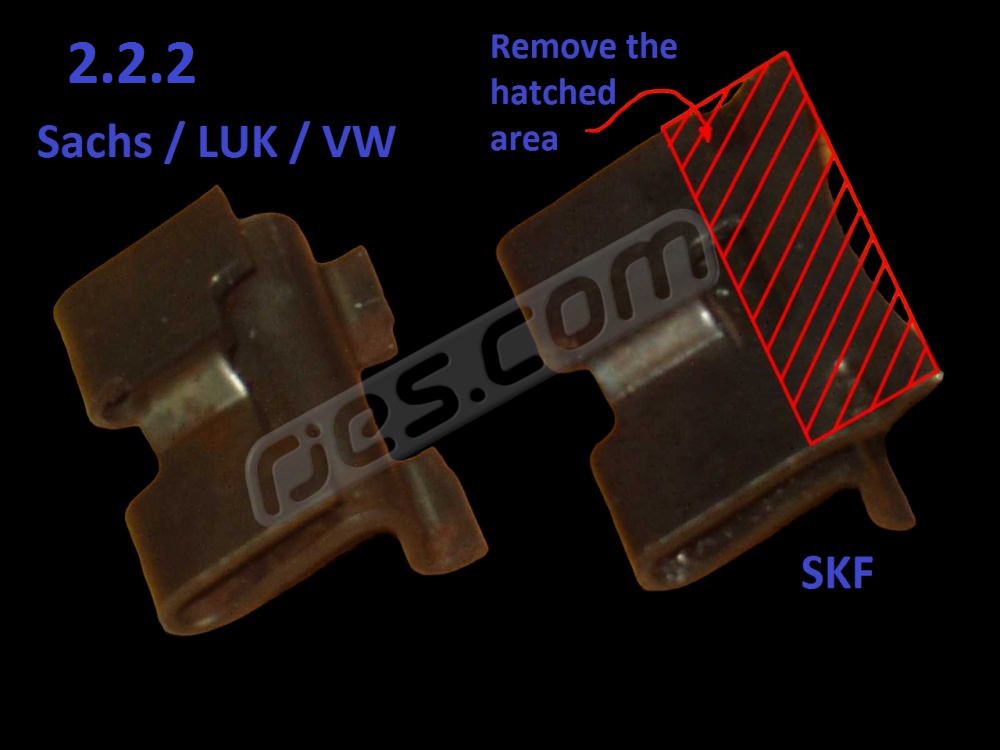
How to shorten the clips from SKF VW release ebarings 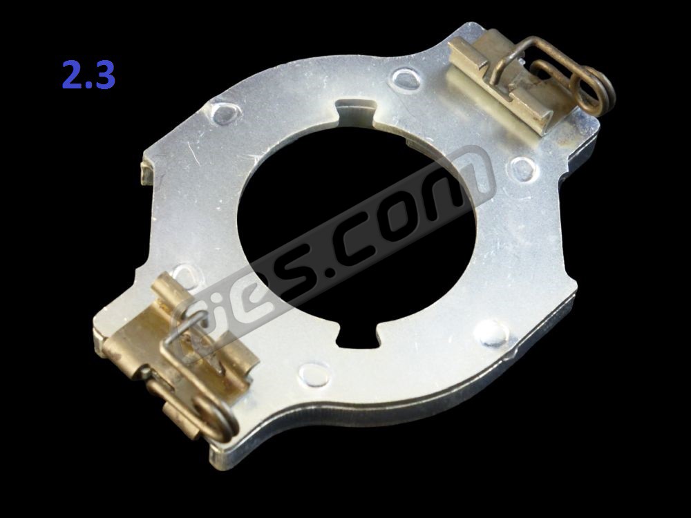
Fit VW clips to adaptor from bell housing kit 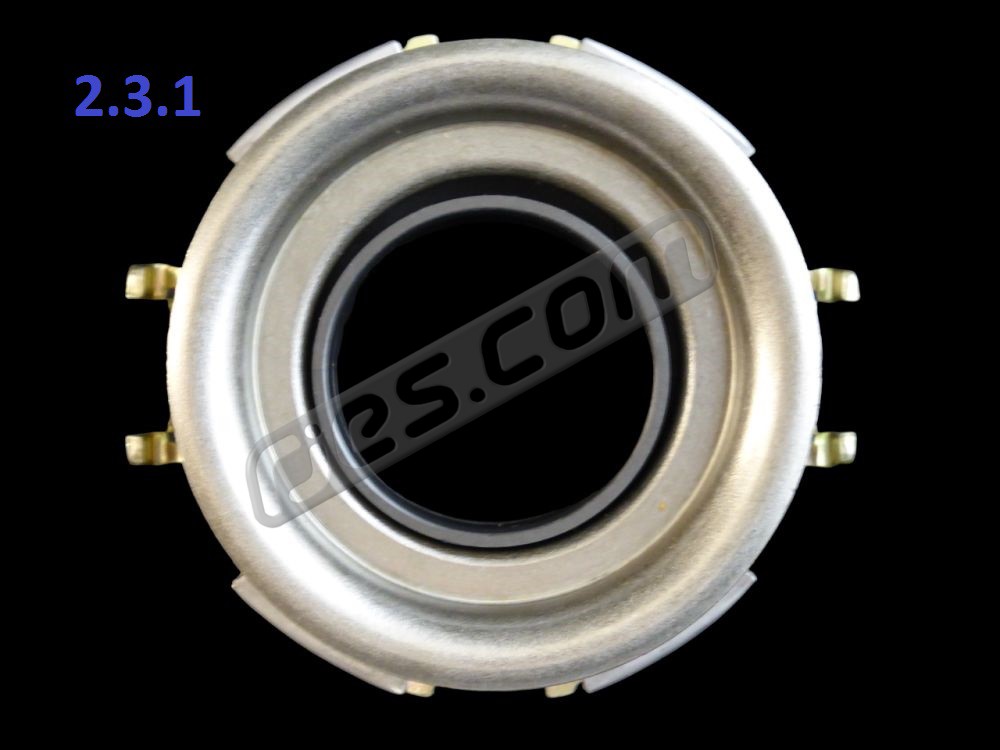
All Subaru release bearings are self aligning 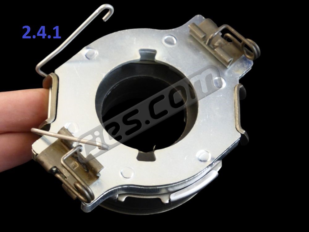
Clip the Subaru bearing to the adaptor 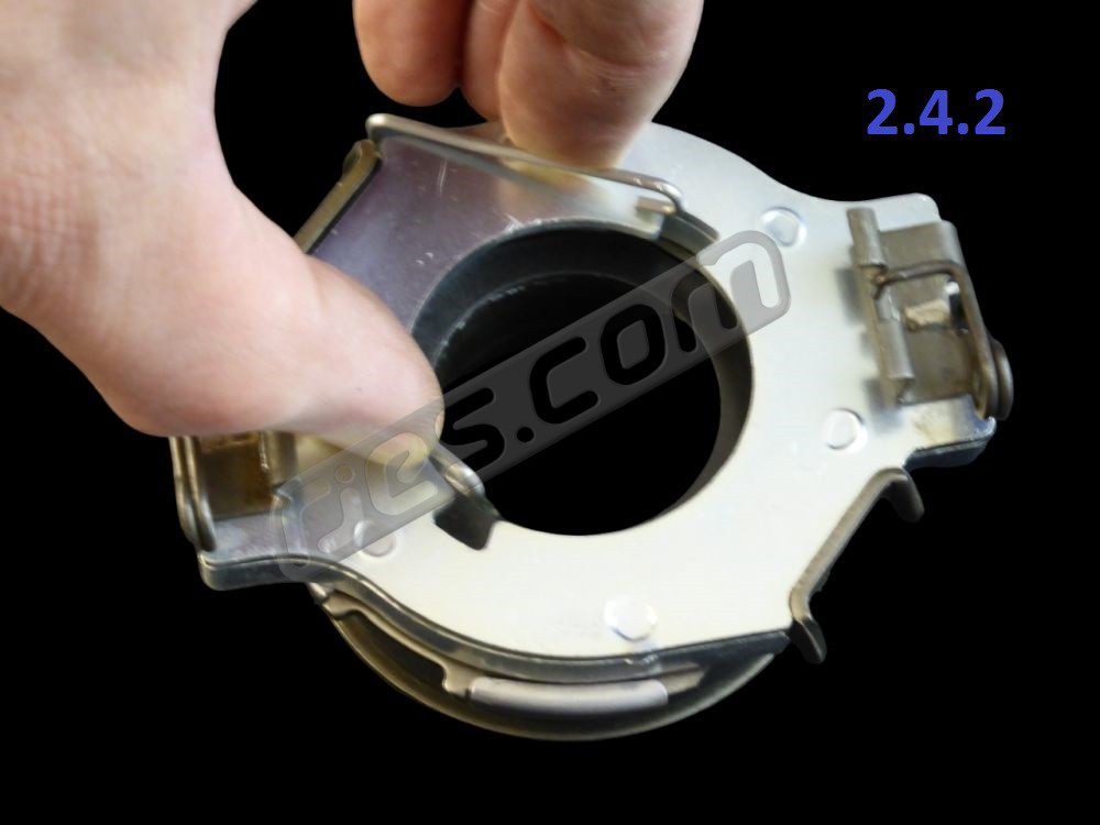
Squeeze clips 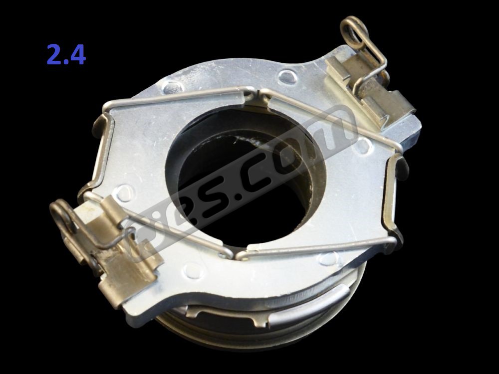
Release bearing assembly 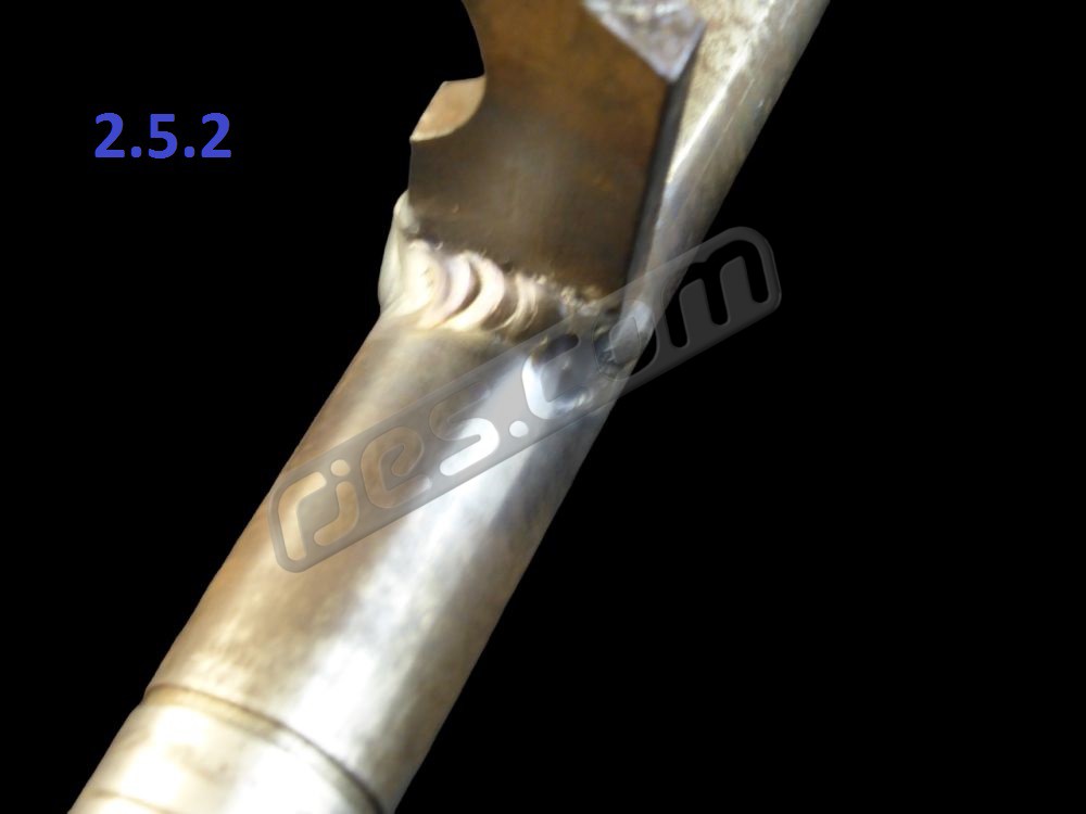
If re-using an original VW clutch release shaft, fully weld the arms to the shaft – they’re a known weak spot 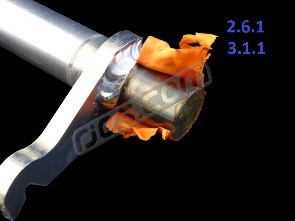
Remove the rubbery coating if using one of our new clutch release shafts 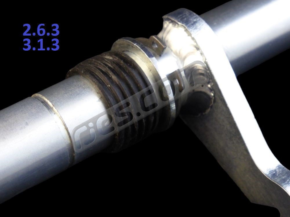
Fit the inner circlip, washer and inner rubber seal to the clutch release shaft 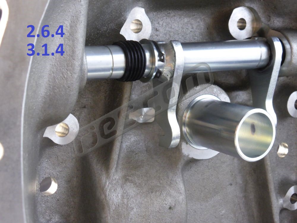
Fit the shaft sub assembly into the bell housing 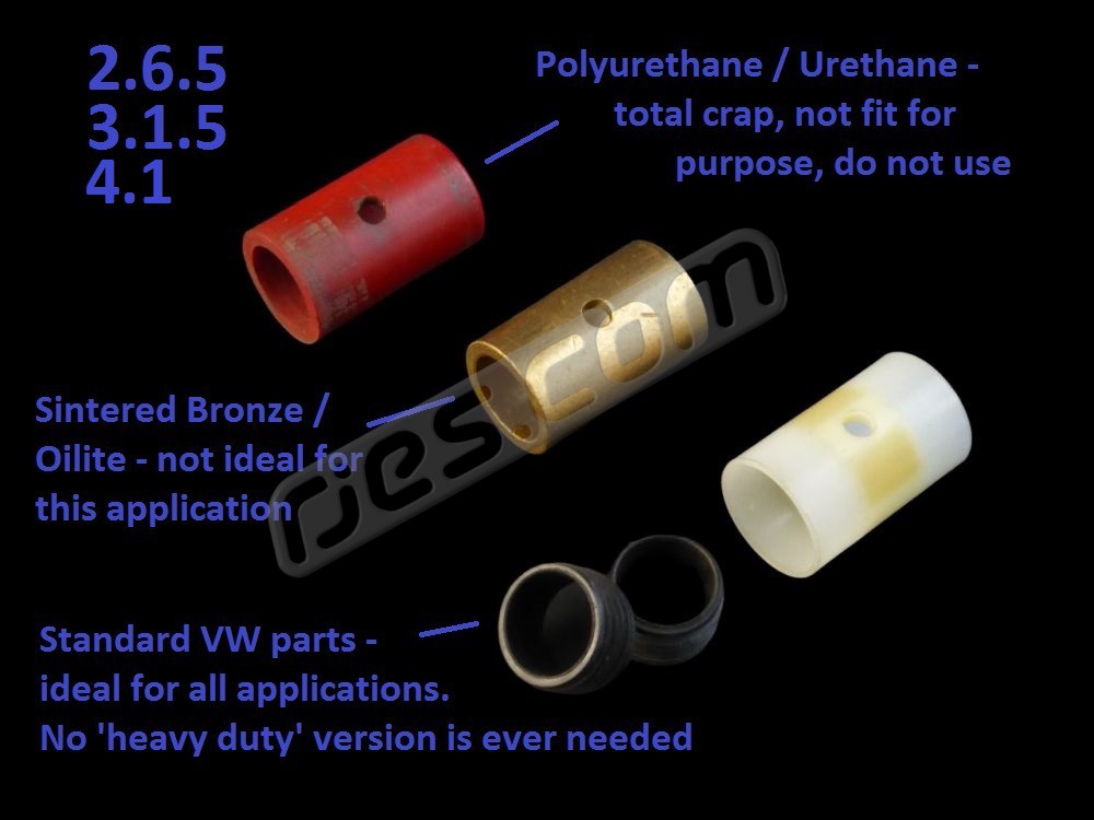
Clutch release shaft bush types 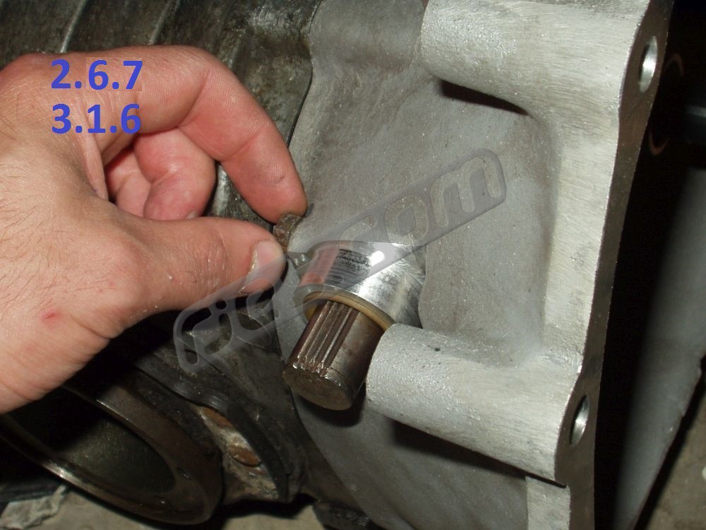
Fit the bush retaining screw, making sure the hole in both bush parts are aligned 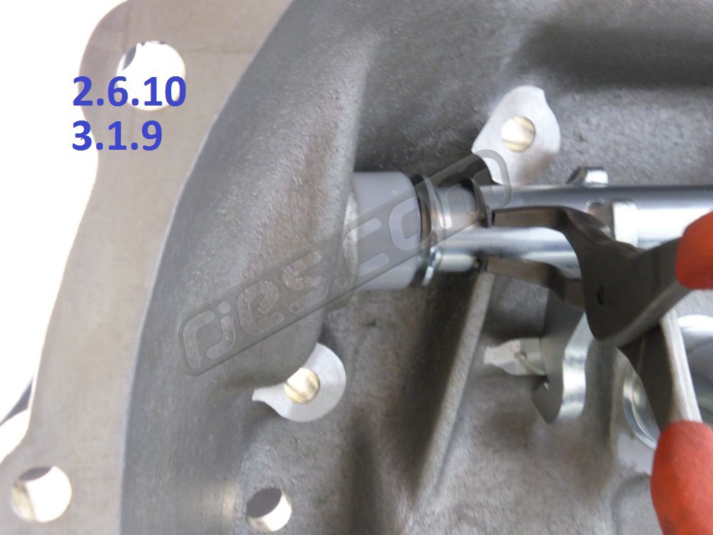
Slide the inner seal and washer along until the circlip fits in its groove 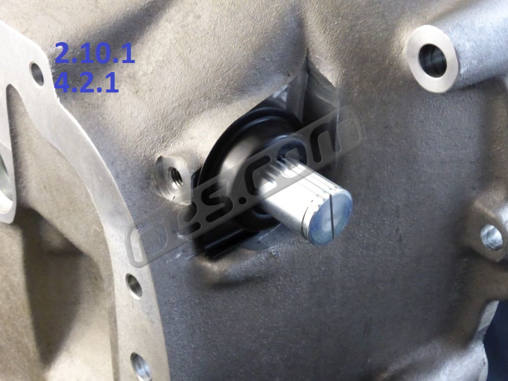
Fit the return spring seat (if cable clutch) 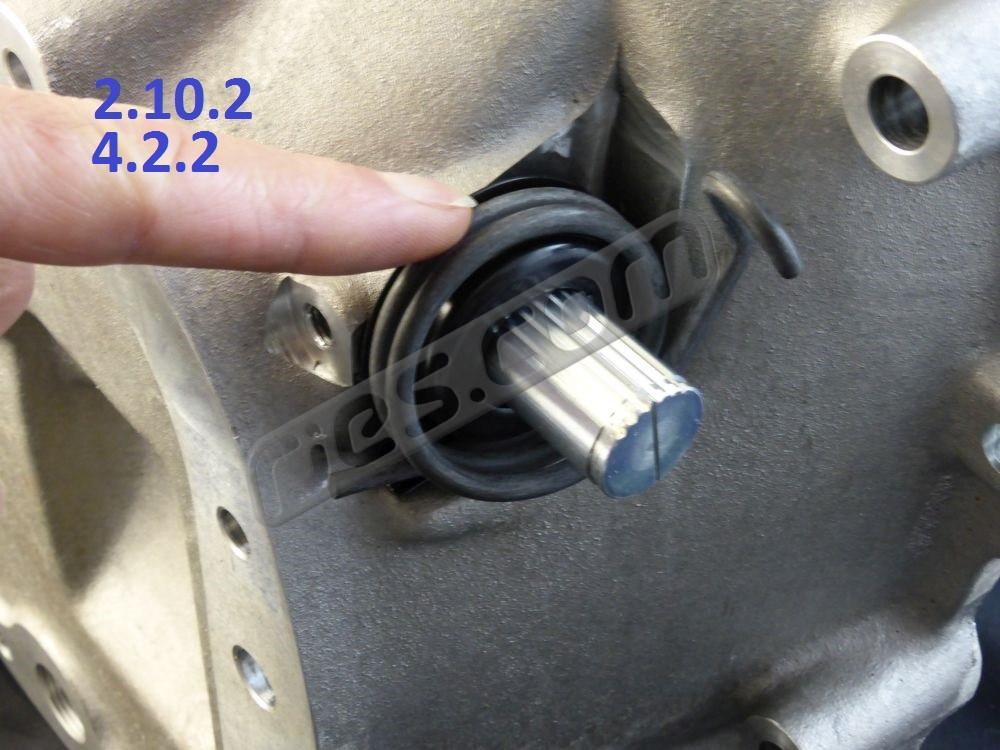
Fit the return spring (if cable clutch) 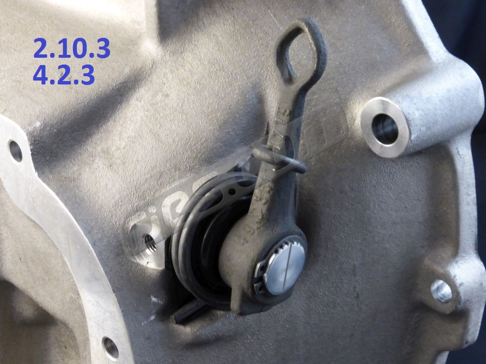
Fit the release shaft arm. See Appendix 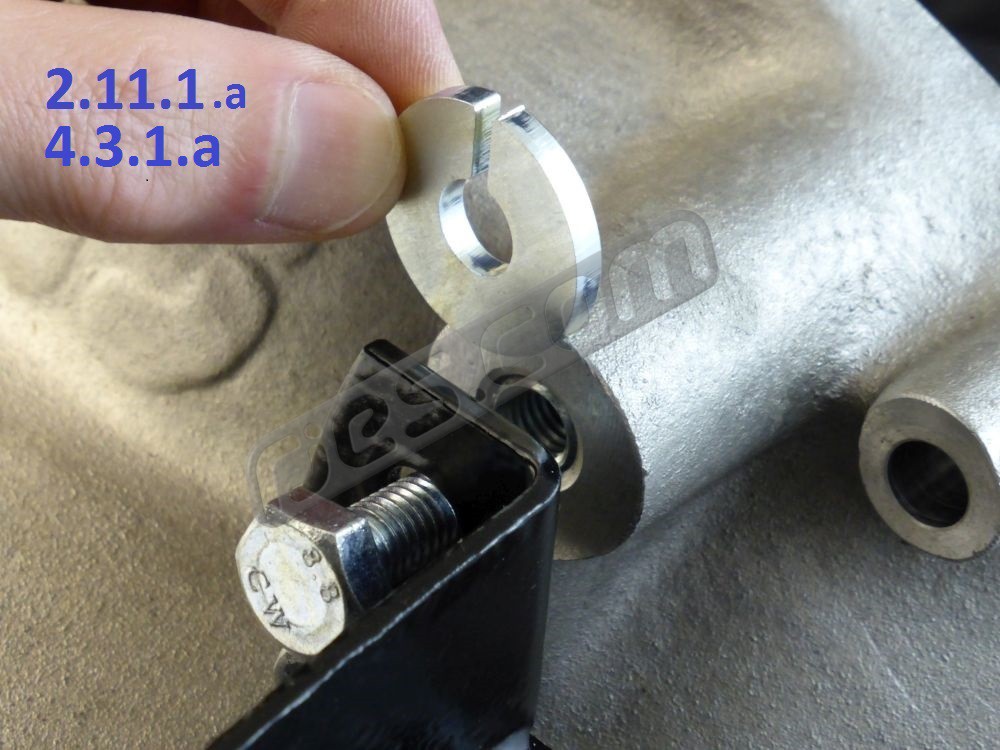
Fit the (petrol) slave cylinder bracket (if hydraulic clutch) 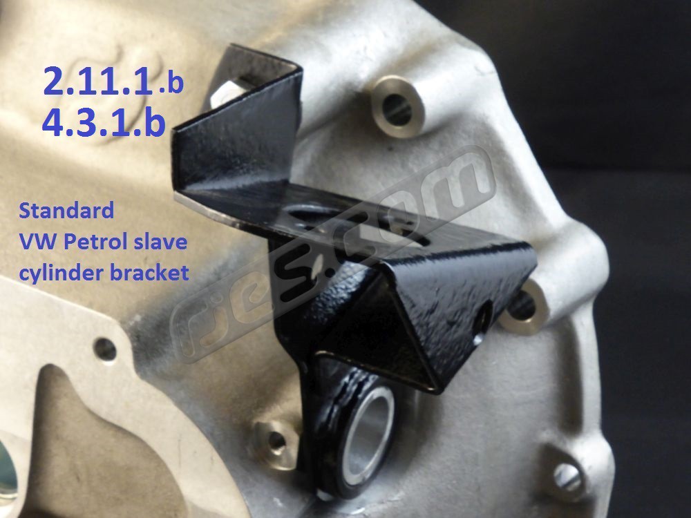
Original VW petrol slave cylinder bracket (if hydraulic clutch) 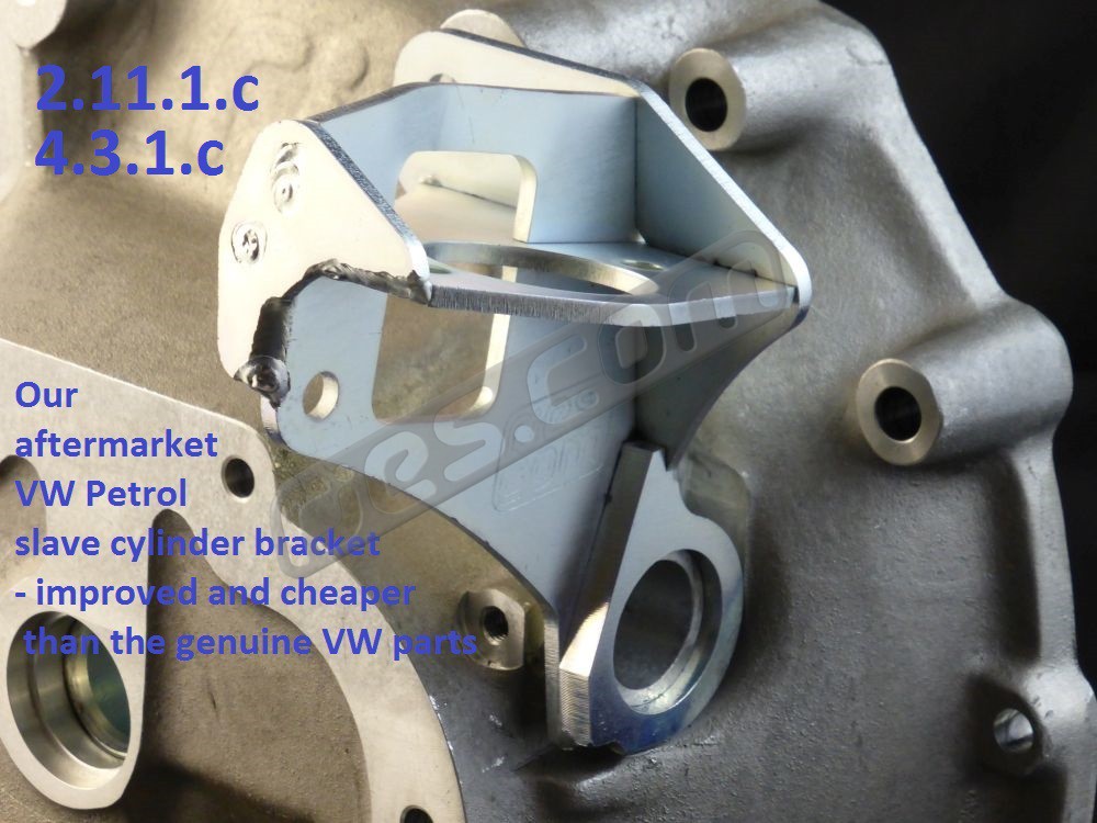
Our reproduction / improved petrol slave cylinder bracket (if hydraulic clutch) 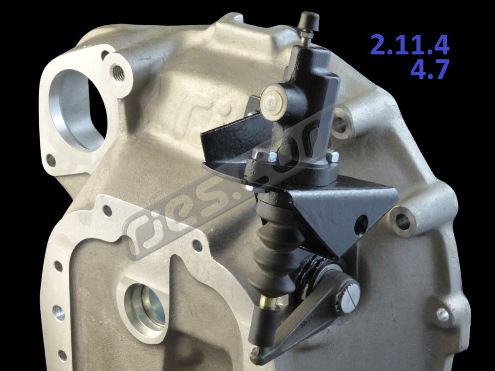
Fit the slave cylinder (if hydraulic clutch)
2. Installation: Clutch Release Shaft and Release Bearing – Naturally Aspirated (push to release clutch)
2.1 If your original VW clutch release shaft is the 16mm diameter type, you will need our 16 to 20mm shaft conversion kit, as the bell housing only works with the stronger and more widely used 20mm version. It contains all of the parts needed. Miss out the rest of section 2.1 and go to 2.2.
If your original VW clutch release shaft is the 20mm diameter type and you intend to re-use it, first check that it is not too worn:
There should be a constant radius where the shaft pushes on the release bearing. If either or both sides has a flat in the middle of the radius, that’s wear. When they wear too much, the release bearing can come loose, and this can cause a lot of damage. Also, if one side wears more than the other (they usually do), the release bearing will be pushed into the clutch diaphragm spring at an angle, which is not good for the clutch. The worn shaft shown in picture 2.1 is borderline if both sides are worn evenly. If it is worn more, or the wear is not even, it is not in good condition.
If you have any doubts about whether the original VW shaft is too worn, replace it. Our replacement shafts are not expensive. They also enable you to use a diesel hydraulic clutch shaft arm (251 141 713 C) in place of the long obsolete petrol arm (251 141 713 B) – something which cannot be done using standard VW parts.
If you are replacing a worm 20mm shaft, you’ll probably want to consider buying a new shaft fitting kit too, so everything is new. This also saves you having to dismantle the clutch release shaft assembly from the VW bell housing, which can be difficult. If so, proceed to 2.2.
2.1.1 Un-hook the release shaft return spring (if your transaxle had a cable clutch) from the release arm with a screw driver or similar. Make sure your fingers are nowhere near the spring as you unhook it from the arm – it’s under a lot of tension.
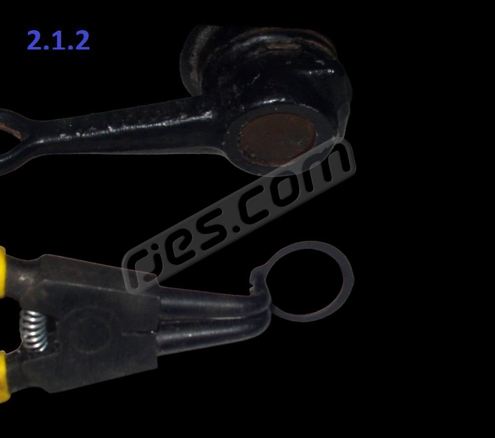
2.1.2 Remove the circlip from the end of the shaft.
2.1.3 Slide the release arm off the end of the shaft. They can be very tight if corroded, but take care not to damage the shaft. Heat may help if it really doesn’t want to come off, but be aware that the bush which the shaft pivots in is plastic, as is the sleeve which it fits into and the seals which keep the dirt out. You’ll need to replace them if you heat the arm to remove it. A puller is a better idea. If you can’t get the puller behind the arm, undo the circlip inside the bell housing, sliding it along the shaft. This will allow you to slide the shaft away out to give better access for the puller. Refit the circlip inside the bell housing back into its groove once the arm is removed. Most generic gear pullers do not fit shafts this small.
DO NOT HAMMER ON THE END OF THE SHAFT. This always expands the diameter of the shaft, making the arm much harder to remove.
2.1.4 Remove the spring and the pressed steel spring guide if your transaxle has a cable clutch.
2.1.5 Remove the fabricated slave cylinder bracket from the bell housing if your transaxle has a hydraulic clutch (unless you’re using a new one).
2.1.6 Remove the threaded pin which retains the release shaft bush from the bell housing. It’s M8, but has an 11mm head.
2.1.7 Push the shaft assembly out from inside the bell housing until the bush assembly is clear of the casting. The circlip and washer will push the plastic bush assembly out of the bell housing. They can be a very tight fit. If the VW bell housing has corroded in the bush bore, the corrosion will probably have trapped the bush so tightly that it is impossible to remove intact.
Pull the bush assembly off the shaft, and the steel washer between the bush assembly and the circlip (which is still on the shaft). The bush assembly consists of an outer plastic sleeve, with a seal, then a bush, then another seal inside.
2.1.8 Check the shaft and plastic bush for wear, and replace as necessary. They are usually in good condition, unless they have been damaged during removal. Even when the shaft has obvious wear from the bush, the bush usually remains unworn.
2.1.9 The shaft can now be removed from inside the bell housing by sliding it across until it comes out of the bronze bush at the opposite end, tilting it, then sliding it back out of the casting.
2.2 Remove the hardened wear plates and bearing retaining spring clips from the VW clutch release bearing:
2.2.1 The clips are just pushed on to the VW bearing, but are quite a tight fit. If they’re badly worn where the release shaft contacts, get some better ones. Used ones are often OK as long as they are not badly worn, and are the same on all ’68 – ’92 busses and ’71 onwards Beetles with Sachs, LUK, or VW clutches. Make sure they’re the same though if you buy a new bearing, as many modern aftermarket parts are cheap copies, not genuine VW. Some high quality aftermarket SKF bearings have a slightly different clip design – see 2.2.2 below. Picture 2.2.1 shows clips which need replacing need replacing – they’re badly worn.
2.2.2 On some SKF aftermarket bearings the spring steel clips needed on the RJES release bearing adaptor are slightly different. The SKF bearing uses these clips to retain the bearing in its casing. VW, Sachs, and LUK bearings have the bearing crimped into its housing. To hold the bearing in on an SKF bearing, the clips are extended on the engine side, as can be seen in the photo. The bearing comes away from the housing when the clips are removed. These clips need to be modified before they will fit the RJES release bearing adaptor, as the extra length fouls on the adaptor. The area hatched red in the photo needs to be removed. The clips are spring steel, so a grinder will have to be used. A very small grinder such as a Dremmel with a 1” cut off disc is ideal.
2.3 Fit the clips from the VW bearing to the Subaru release bearing adaptor.
2.3.1 If the Subaru release bearing looks like it is not concentric, this is normal. All Subaru clutch release bearing types are self-aligning.
2.4 Fit the Subaru release bearing to the release bearing adaptor plate with the two wire clips.
2.4.1 Hook the central part of the clip around the Subaru bearing.
2.4.2 Hold the bearing and adaptor together, and hook each end of each wire clip into its groove in the adaptor.
2.5 Prepare the release shaft for use with the Subaru release bearing:
2.5.1 With the release shaft removed from the bell housing, trial fit the adaptor plate / release bearing assembly onto the cross shaft. Rock the bearing / adaptor assembly on the shaft, and check that it moves freely.
2.5.2 If you are re-using an original VW clutch release shaft, the arms welded to it are a known weak spot. Each arm is only spot welded to the shaft in two places, and then mig tacked with at one end. Fully welding the arms on to increase strength is common practice, and is highly recommended when installing a Subaru conversion.
Any welding process is suitable, but tig is very preferable. It is very difficult to get weld penetration into the shaft with mig or arc welding because it is so much thicker than the arm. Many aftermarket versions of the shafts suffer from this – especially the non-plated version sold by JP Group (they sell two types under the same part number). They are welded on one side only with what looks like a good mig fillet. But it has almost no penetration into the shaft at all. If you break one off (very easy), it leaves the shaft surface intact.
2.6 Fit the clutch release shaft and its bushes into the new bell housing.
2.6.1 Remove the rubbery coating from the small end if you are using one of our new clutch release shafts. Lightly grease where it was with general purpose grease.
2.6.2 Slide the inner circlip into the shaft as far as it will go (past its groove), followed by the steel washer.
2.6.3 Cover one of the rubber seals in grease and slide it right up to the circlip and washer (shown here without the grease).
2.6.4 Fit the shaft through the bell housing from the inside.
2.6.5 DO NOT use an aftermarket polyurethane (urethane) one piece bush which replaces the standard VW two piece bush and rubber seals. They are not fit for purpose and can cause big problems. You will never find any kind of OEM automotive or industrial bushes for applications like this made from cast urethane because it’s not a suitable material (like the genuine VW parts, they’re always made from nylon or acetal).There is no need for any kind of supposed heavy duty clutch release shaft bush – the standard VW parts are far superior for all applications. The aftermarket sintered bronze / Oilite bushes are also not ideal.
2.6.6 Push the VW plastic clutch release shaft bush onto the end of the shaft and into the bore in the bell housing, taking care to make sure that you align the plastic sleeve and the bush inside it with the hole in the bell housing. It needs to be almost perfectly aligned before the retaining pin can be fitted. The sleeve and bush will be damaged if you screw the pin in with tools without the holes all being aligned. Making sure they are aligned is very easy if the gearbox is not in the VW – just make sure you look into the tapped M8 hole in the bell housing to check. You’ll need to use a mirror if the transaxle is still fitted though, and this makes it harder.
2.6.7 Screw the retaining pin in by hand. If the holes are all aligned OK, it should go in until the captive spring washer is about to get compressed. Carefully tighten it up to 15 Nm (11 ft lb).
2.6.8 Check the shaft turns smoothly. It should not stick in any position.
2.6.9 Cover the second rubber seal in grease and push it along the shaft and into the gap between the shaft and bush. Wipe off any excess grease.
2.6.10 Slide the inner rubber bush, washer and inner circlip along the shaft until the circlip is in its groove.
2.7 Very lightly grease the release bearing guide tube.
2.8 Fit the release bearing / adaptor plate assembly to the new bell housing. If you are refitting a used Subaru release bearing, DO NOT clean it with solvent, as this can wash grease out of the sealed bearing. If the bearing does not rotate smoothly and silently, it needs replacing. Lightly grease the cross shaft where it contacts the bearing, slide the bearing over the bell housing guide tube, rotate the shaft, and hook the bearing retaining spring clips around the release shaft.
2.9 Rotate the shaft so that the bearing slides up and down the guide tube, to check that everything moves smoothly.
2.10 If your VW has a cable clutch:
2.10.1 Fit the pressed steel return spring guide.
2.10.2 Fit the cross shaft return spring around the release shaft.
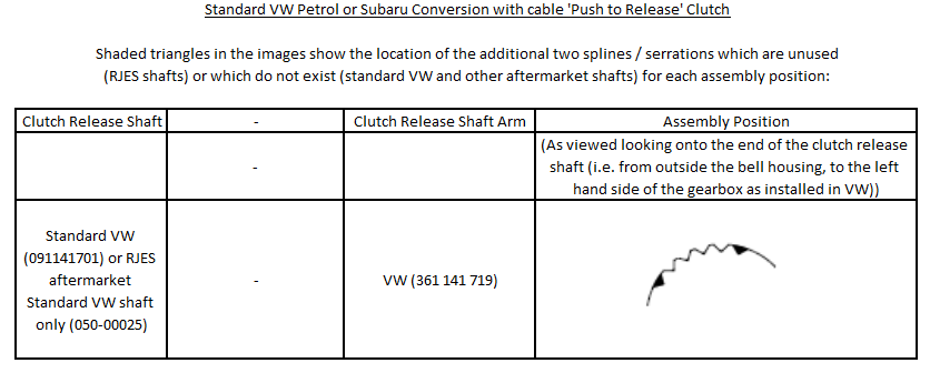
2.10.3 Fit the clutch arm (this must be VW part 361 141 719) and its retaining circlip. If using out clutch release shaft 050-00025, make sure you the use the centre 4 of the 6 serrations as shown below. Anti-seize compound between the arm and shaft is a good idea
2.11 If your VW has a hydraulic clutch:
2.11.1 The bell housing kit is designed to use the petrol slave cylinder bracket only. You cannot use the diesel slave cylinder bracket without significantly modifying it to make it fit in the petrol location. This is nor recommended. If you’re using a diesel gearbox or your petrol bracket needs replacing, the genuine VW parts are still available, but ridiculously expensive. We make an aftermarket version which is considerably cheaper which is a considerably better design (if you’ve ever had the misfortune of having to replace a slave cylinder, you’ll know why the original design is so bad).
Fit the petrol slave cylinder bracket around the boss on the bell housing. Make sure it is squarely pushed up against the flat face around the boss. Hold it in place with the M10 x 20 retaining screw, using the 4mm thick washer with a slot in it to fill the gap between the bracket and the bell housing, screwed into the steel insert in the casting. Tighten to 45 Nm (33 ft lbs).
2.11.2 Fit the VW brace which ties the slave cylinder to the transaxle casing just above the LH drive shaft flange. Don’t miss this out – the bracket will rock on the bell housing without the brace, damaging the casting.
2.11.3 Fit the slave cylinder.
2.11.4 Fit the VW clutch arm and its retaining circlip on the end of the clutch shaft. Anti-seize compound between the arm and shaft is a good idea. If using one of our clutch shafts, the arm can fit in three different locations, and there are two different arms (petrol and diesel).
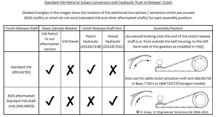
- If you are using a standard VW release shaft, you must use petrol VW release arm 251 141 713 B (i.e. you cannot use diesel arm 251 141 713 C).
- If you are are using our aftermarket VW release shaft 050-00025, you can use either petrol release shaft arm 251 141 713 B or its diesel equivalent 251 141 713 C, but you have to be careful to get the arm position on the shaft correct
….as shown below:
Remove the rubbery coating if using one of our new clutch release shafts Fit the inner circlip, washer and inner rubber seal to the clutch release shaft Fit the shaft sub assembly into the bell housing Clutch release shaft bush types Fit the bush retaining screw, making sure the hole in both bush parts are aligned Slide the inner seal and washer along until the circlip fits in its groove 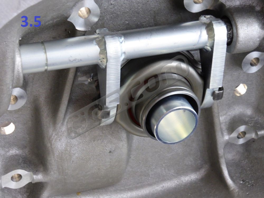
3.5 Check that the release bearing moves smootly along the guide tube
3.1 If you are intending to re-use the release shaft bush, seals and washer from your VW bell housing, follow 2.1.1 – 2.1.9 above to remove them. You may end up wishing you’d bought new parts though if the arm is stuck on the shaft.
DO NOT use an aftermarket polyurethane (urethane) one piece bush which replaces the standard VW parts. They are not fit for purpose and can cause big problems. There is no need for any kind of supposed heavy duty clutch release shaft bush – the standard VW parts are far superior for all applications. The aftermarket sintered bronze / Oilite bushes are also not ideal.
3.1.1 Remove the rubbery coating from the small end of the new clutch release shaft, and lightly grease where it was with general purpose grease.
3.1.2 Slide the inner circlip onto the shaft as far as it will go (past its groove), followed by the steel washer.
3.1.3 Cover one of the rubber seals in grease and slide it right up to the circlip and washer.
3.1.4 Fit the shaft through the bell housing from the inside.
3.1.5 DO NOT use an aftermarket polyurethane (urethane) one piece bush which replaces the standard VW parts. They are not fit for purpose and can cause big problems. There is no need for any kind of supposed heavy duty clutch release shaft bush – the standard VW parts are far superior for all applications. The aftermarket sintered bronze / Oilite bushes are also not ideal.
Push the VW plastic clutch release shaft bush onto the end of the shaft and into the bore in the bell housing, taking care to make sure that you align the plastic sleeve and the bush inside it with the hole in the bell housing. It needs to be almost perfectly aligned before the retaining pin can be fitted. The sleeve and bush will be damaged if you screw the pin in with tools without the holes all being aligned. Making sure they are aligned is very easy if the gearbox is not in the VW – just make sure you look into the tapped M8 hole in the bell housing to check. You’ll need to use a mirror if the transaxle is still fitted tough, and this make it a lot harder
3.1.6 Screw the retaining pin in by hand. If the holes are all aligned OK, it should go in until the captive spring washer is about to get compressed. Carefully tighten it up to 15 Nm (11 ft lb).
3.1.7 Check the shaft turns smoothly. It should not stick in any position.
3.1.8 Cover the second rubber seal in grease and push it along the shaft and into the gap
3.1.9 Slide the inner rubber bush and washer along the clutch release shaft until the washer touches the bush, and fit the inner circlip into its groove.
3.2 Fit the new ‘pull to release clutch’ slave cylinder bracket from the bell housing kit onto bell housing using the M10x20 set screw, 4mm thick washer and the original VW M8 set screw. Tighten the M10 bolt to 45 Nm (33 ft lb).
3.3 Rotate the cross shaft back and forth, so the bearing slides along the guide tube. Check that the release bearing moves smoothly.
3.4 Very lightly grease the release shaft where it will contact the bearing, and the release bearing guide tube.
3.5 Rotate the shaft so that the bearing slides back and forth along the guide sleeve. Check that it all still moves smoothly.
3.6 Fit the release arm to the end of the cross shaft:
- If you have a hydraulic clutch and are using a standard VW release shaft, you must use petrol VW release arm 251 141 713 B (i.e. you cannot use diesel arm 251 141 713 C).
- If you have a hydraulic clutch and are are using our aftermarket VW release shaft 050-00025, you can use either petrol release shaft arm 251 141 713 B or its diesel equivalent 251 141 713 C, but you have to be careful to get the arm position on the shaft correct
- If you have a cable clutch use VW release shaft arm 361 141 719
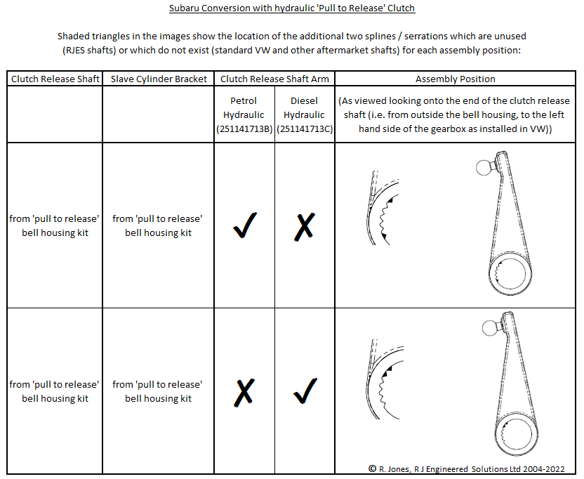
Lubricate the interface with an anti-seize compound such as copper grease.
3.7 Fit the VW T25 / Vanagon clutch slave cylinder and pushrod to the new bracket. Check that the bleed screw has not seized up on the slave cylinder before fitting, and replace as necessary.
3.8 Bend the slave cylinder pipe to suit, and tighten all the pipe fittings. If you have a late model with a plastic clutch pipe, note that the banjo fitting in the end can be turned in the pipe to get the best fit.
3.9 Bleed the clutch if you have disconnected the slave cylinder during the conversion. Because the slave cylinder has to be fitted with the pushrod end higher than the bleed screw end for the turbo clutch, bleeding the clutch with the slave cylinder in situ is impossible. Simply unbolt it from it’s bracket so it hangs by its pipe. If you have a metal pip e going to your cylinder, you may also have to temporarily unbolt the bracket between the other end of the pipe and gearbox. Bleed the clutch with the cylinder hanging so the bleed screw is the highest part, and refit it.
Clutch release shaft bush types Fit the return spring seat (if cable clutch) Fit the return spring (if cable clutch) Fit the release shaft arm. See Appendix Fit the (petrol) slave cylinder bracket (if hydraulic clutch) Original VW petrol slave cylinder bracket (if hydraulic clutch) Our reproduction / improved petrol slave cylinder bracket (if hydraulic clutch) 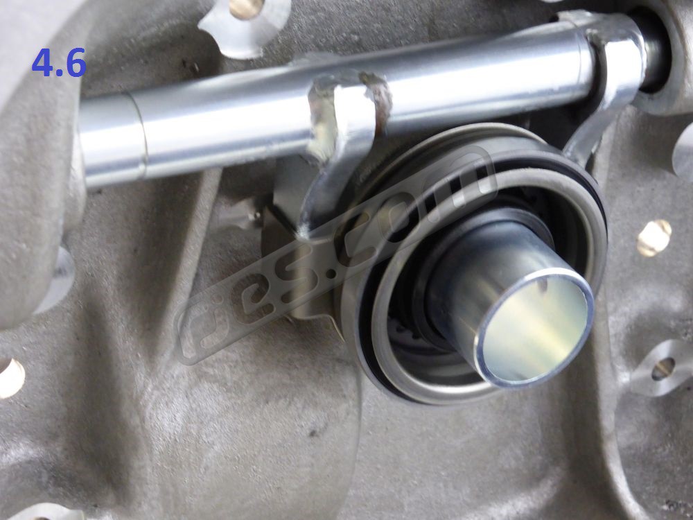
4.6 Check that the release bearing moves smoothly along the guide tube Fit the slave cylinder (if hydraulic clutch)
4.1 If you are intending to re-use the release shaft bush, seals and washer from your VW bell housing, follow 2.1.1 – 2.1.9 above to remove them. You may end up wishing you’d bought new parts though if the arm is stuck on the shaft.
DO NOT use an aftermarket polyurethane (urethane) one piece bush which replaces the standard VW parts. They are not fit for purpose and can cause big problems. There is no need for any kind of supposed heavy duty clutch release shaft bush – the standard VW parts are far superior for all applications. The aftermarket sintered bronze / Oilite bushes are also not ideal.
4.1.1 Follow 2.6 above to install the new clutch release shaft into the bell housing.
4.2 If your VW has a cable clutch:
4.2.1 Fit the pressed steel return spring guide.
4.2.2 Fit the cross shaft return spring around the release arm.
4.2.3 Fit the clutch arm (this must be VW part 361 141 719) and its retaining circlip. If using out clutch release shaft 050-00025, make sure you the use the centre 4 of the 6 serrations as shown below. Anti-seize compound between the arm and shaft is a good idea
4.3 If your VW has a hydraulic clutch:
4.3.1 The bell housing kit is designed to use the petrol slave cylinder bracket only. You cannot use the diesel slave cylinder bracket without significantly modifying it to make it fit in the petrol location. If you’re using a diesel gearbox or your petrol bracket needs replacing, the genuine VW parts are still available, but ridiculously expensive. We make an aftermarket version which is considerably cheaper which is a considerably better design (if you’ve ever had the misfortune of having to replace a slave cylinder, you’ll know why the original design is so bad).
Fit the petrol slave cylinder bracket around the boss on the bell housing. Make sure it is squarely pushed up against the flat face around the boss. Hold it in place with the M10 x 20 retaining screw, using the 4mm thick washer with a slot in it to fill the gap between the bracket and the bell housing, screwed into the steel insert in the casting. Tighten to 45 Nm (33 ft lbs).
Note, if you need to refit or remove the slave cylinder bracket with the clutch shaft installed and the arm fitted onto the end, but do not have the engine bolted to the bell housing, this can easily be done without having to take the arm off the shaft. Temporarily slide the inner clutch release shaft circlip along the shaft and remove the release bearing. This enables you to slide the shaft out enough to get the slave cylinder bracket on or off. Just don’t forget to make sure you put the circlip back into its groove.
4.3.2 Fit the VW brace which ties the slave cylinder to the transaxle casing just above the LH drive shaft flange. Don’t miss this out – the bracket will rock on the bell housing without the brace, damaging the casting.
4.3.3 Fit the slave cylinder.
4.3.4 Fit the VW clutch arm and its retaining circlip on the end of the clutch shaft. Anti-seize compound between the arm and shaft is a good idea. If using one of our clutch shafts, the arm can fit in three different locations, and there are two different arms (petrol and diesel).
- If you are using a standard VW release shaft, you must use petrol VW release arm 251 141 713 B (i.e. you cannot use diesel arm 251 141 713 C).
- If you are are using our aftermarket VW release shaft 050-00025, you can use either petrol release shaft arm 251 141 713 B or its diesel equivalent 251 141 713 C, but you have to be careful to get the arm position on the shaft correct
….as shown below:
4.3 Rotate the cross shaft back and forth, so the bearing slides along the guide tube. Check that the release bearing moves smoothly.
4.4 Very lightly grease the release shaft where it will contact the bearing, and the release bearing guide tube.
4.5 Fit the release bearing
4.6 Rotate the shaft so that the bearing slides back and forth along the guide tube. Check that it all still moves smoothly.
4.7 Fit the VW T25 / Vanagon clutch slave cylinder and pushrod to the new bracket. Check that the bleed screw has not seized up on the slave cylinder before fitting, and replace as necessary.
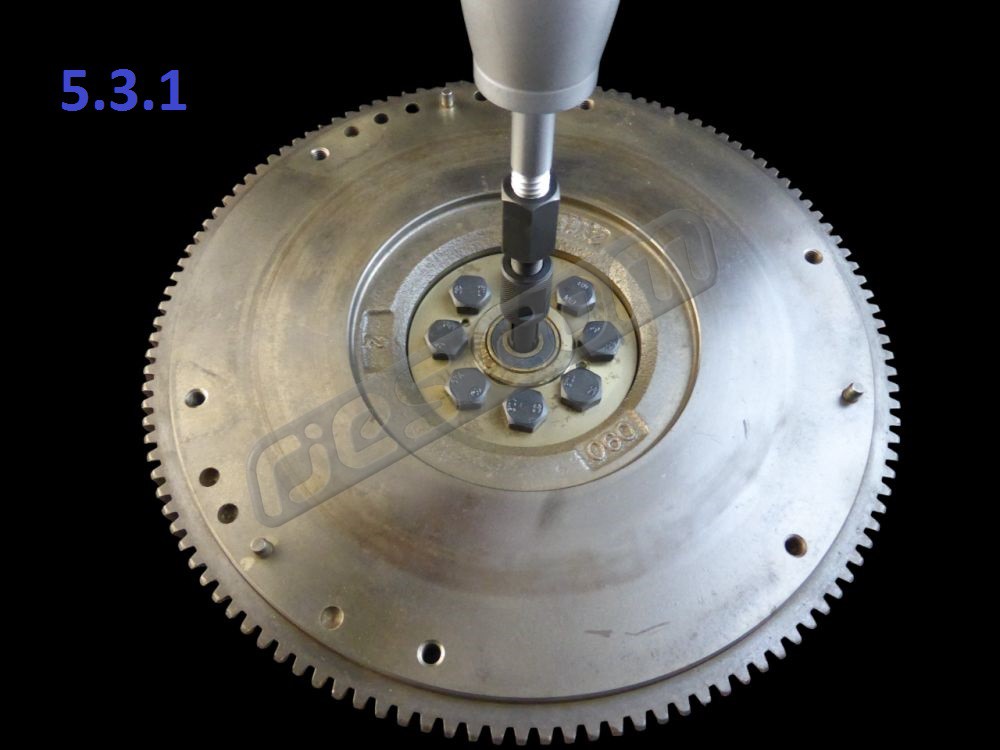
Remooving Subaru pilot / spigot bearing with an internal puller 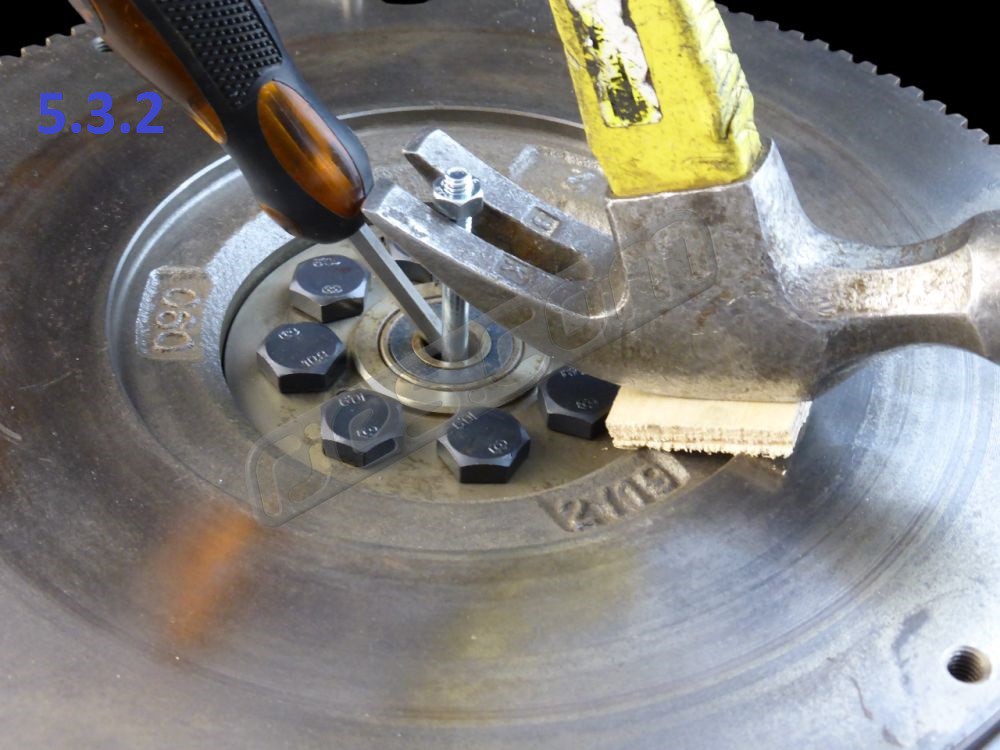
Removing pilot / spigot bearing with a bolt, screwdriver and claw hammer 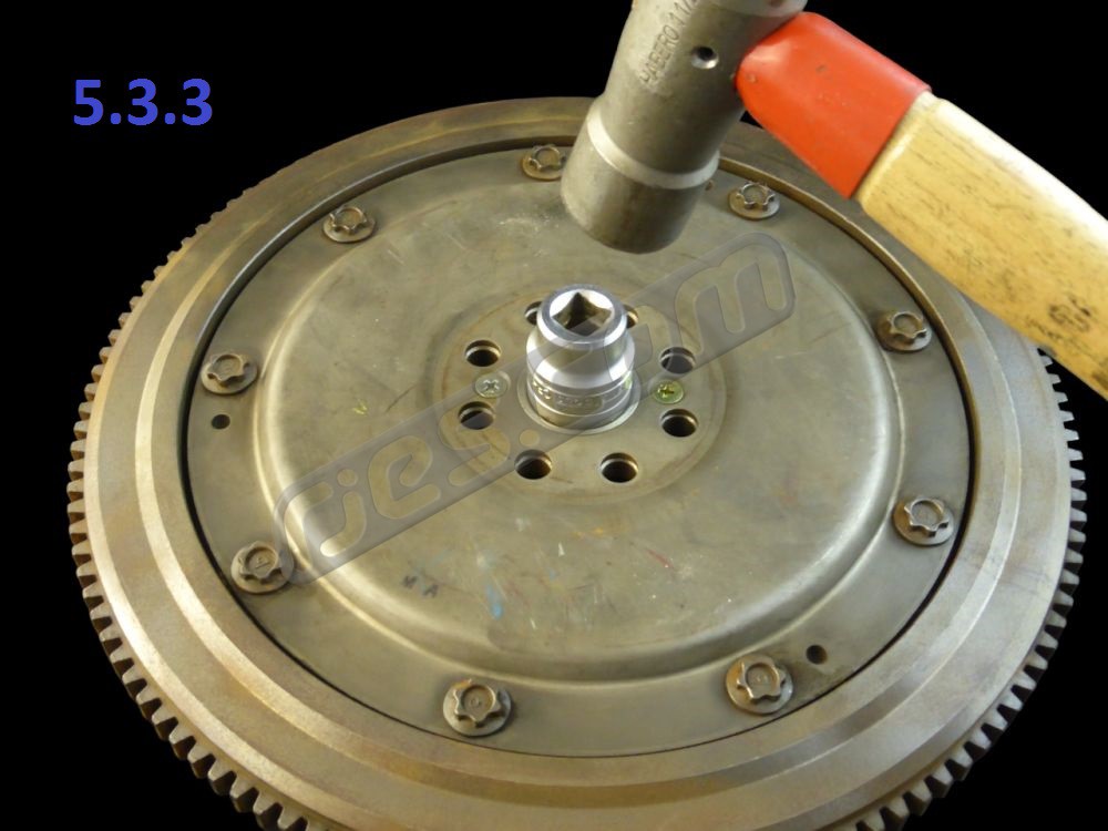
Removing Subaru pilot / spigot bearing with flywheel removed 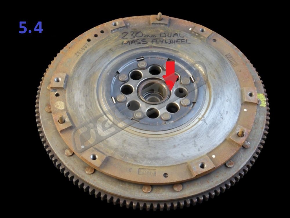
Circlip location if you need to dismantle a Subaru / Valeo DMF to access the crank bolts. Note – you’ll destroy the flywheel in the process.
5.1 Check Subaru parts:
5.1.1 Check that the two engine alignment dowels have remained in the Subaru transmission – i.e. that you have two dowel holes in the engine. Sometimes they stay in the engine. If not, either pull them out of the holes in the engine (this can be very difficult, and is not worth trying), or knock the relevant dowel(s) out of the new bell housing. If you remove dowel(s) from your bell housing, make sure the casting is supported properly. Remove the dowel(s) as required by tapping them out from either side with a hammer and punch.
5.1.2 For around 10 years from about MY92, EJ series engines had plastic breather cover. These are renowned for cracking and leaking oil, and are not accessible until the flywheel is removed from the crank. Outside this approximate date range they all used metal covers which don’t leak. If yours is likely to have a plastic cover, or if there is oil leaking from between the crank case and flywheel, you should check the breather cover even if that means taking the flywheel off just for this, while doing so is easy.
Don’t try to re-seal a leaking flywheel cover – the leak is almost always from a crack from one of the screw holes which isn’t repairable. The fix is to replace it with a metal breather cover. Either a genuine Subaru one, or the one we make.
5.2 Manual Transmission Subaru Engines (proceed to 4.3 if your engine is from an automatic transmission Subaru):
5.2.1 Remove the clutch pressure plate from your Subaru engine. Undo the six M8 screws one turn at a time, alternating across the pressure plate to avoid distorting it. Remove it and the disc.
5.2.2 Clean the clutch dust off the flywheel. Clutch dust is dangerous – follow the precautions in either a VW or Subaru manual on not inhaling any dust, and how to clean it off the components.
5.3 If your engine has a single mass flywheel the pilot / spigot bearing in the centre needs to be removed so the replacement from bell housing kit can be installed in its place:
5.3.1 The easiest / quickest way to remove the Subaru pilot bearing is to pull it out with an internal bearing puller on a slide hammer.
5.3.2 …..or you can also remove the pilot / spigot bearing without taking the flywheel off the crank using an M6 nut and bolt, a claw hammer, a block of wood, and a screwdriver. Screw the nut onto the bolt, and hook the head of the bolt behind the inner race of the Subaru pilot bearing. Put a flat bladed screwdriver into the bearing too, to wedge the bolt head behind the bearing Adjust the nut so that the claw hammer can be used to pull on the bolt. Place a piece of wood between the hammer and the flywheel to avoid damaging flywheel.
5.3.3 …..or you can remove the flywheel from the crank. The bearing is fitted in a through hole which also centres the flywheel on the crank, so you can tap the pilot bearing out from the engine side.
5.4 If your engine has the Valeo dual mass flywheel and clutch you need to remove them and fit the relevant single mass equivalent and its clutch. Removing the Valeo DMF isn’t straight forward. The bolts don’t have hex heads, they’re Torx Plus. Anyone who has not come across Torx Plus before will probably mistake them for Torx, and try to undo them with a normal Torx bit. This is a mistake, and often breaks the bolt heads (as does trying to undo them with an Allen bit). Torx Plus is a heavier duty version of Torx, and although they look very similar, they’re not interchangeable. The correct Torx Plus but size is TP50. Torx Plus bits used to be incredibly hard to get. Back in around 2003 we had to order a set from the US after not being able to find any tool brand who had them in stock in the UK. They’re easier to get now, but still not exactly common.
The other problem you’ll have if removing a Valeo DMF is that the holes in the clutch friction face do not line up with the bolts, so you can’t get the Torx Plus bit into the bolt heads square. If you don’t need to use the DMF again, you can remove the friction face from the DMF which gives perfect access to the bolts – but you’ll never get the DMF back together again. How to get the DMF apart is not immediately obvious. The friction face is held on by a circlip, but it’s very hard to see. It is in the groove highlighted by the red arrow in the picture. Remove it and pry the friction face away from the rest of the flywheel. Once it’s removed you have perfect access to the Torx Plus bolts
If the SMF you’re replacing the DMF with has a pilot / spigot bearing in the centre, check its bore diameter. If it is 15mm you already have the right bearing (we sometimes pre-install the bearing from your bell housing kit if you buy a flywheel at the same time). If it is 12mm, tap the bearing out of the flywheel bore.
5.5 Automatic transmission Subaru engines:
Automatic transmission Subaru engines have no flywheel. Instead they have a torque converter drive plate made from thin sheet metal. You will need to remove this and fit a suitable flywheel. Subaru use many different types of flywheel. See Appendix B below for information on Subaru flywheel types. We stock new flywheels for the most common applications.
5.5.1 Lock the drive plate so you can undo the bolts without turning the crank, remove the rubber plug fitted into the crankcase (behind the flywheel, below the throttle position sensor), Turn the crank until you see a slot in the drive plate. Subaru dealers use a special tool, but a large screwdriver works just as well. Put it through the slot to jam the drive plate against the crankcase.
5.5.2 Undo the eight drive plate bolts. Remove the drive plate.
You will need to find a good used flywheel to convert your automatic transmission engine. See Appendix B. Try breakers, Subaru engine specialists, or Ebay. Also get the flywheel mounting bolts too if possible – the ones which hold the drive plate will be too short for a flywheel. If you can’t get the bolts (Subaru part No.800210660), they’re cheap from the dealers (£5 for all 8).
5.5.3 An alternative way to remove the bearing from the flywheel is to tap it out from the opposite side. This means removing the flywheel. The bearing is fitted in a through hole, which also centres the flywheel on the crank spigot. Eight M10 bolts hold the flywheel to the crank, and unlike the VW engines, removing the flywheel does not disturb the crank oil seal.
Most Subaru’s up to ’99 use hexagon headed flywheel bolts. You’ll need to lock the flywheel to undo the bolts. Wedge a VW flywheel lock tool in the ring gear teeth in the starter motor gap if you have one – this works very well. Alternatively use a very long flat bladed screwdriver between two of the ring gear teeth to stop the flywheel turning against the crank case. Remove the bolts and lift the flywheel off. Tap the pilot bearing out of the flywheel, and refit the flywheel. Tighten the bolts with a torque wrench to 69 – 74.5Nm (51 to 55 fl lb). Some low to medium strength thread lock on the threads would not be a bad idea.
5.5.4 If you are converting an auto engine for use in a manual VW, there is one other simple part which you should fitting too if your engine is newer than MY97. Manual transmission MY98 à Subaru engines have a cam belt guide which is not fitted to the automatic models. It stops the belt jumping teeth on the crank pulley, and is fitted with two M6 x 1.0 x 10mm screws into the oil pump. We stock these. Set the clearance from the belt guide to the belt at 1.0mm. You can only fit them to pre MY98 engines if the oil pump has been changed or the later design with the mounting bosses.
Fit the wire spacer ring 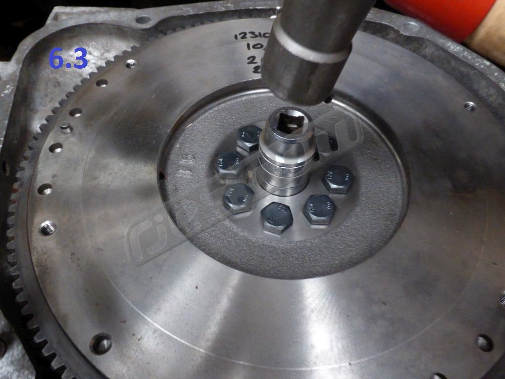
Fit the pilot / spigot bearing from the bell housing kit. Always use Loctite if not using a genuine Subaru or Exedy flywheel
6.1 If you removed a dual mass flywheel or torque converter drive plate, you’ll need new longer flywheel bolts to suit your single mass flywheel. Use either the genuine Subaru parts or a proven aftermarket version such as the ones we stock. They are an uncommon spec, so you’re not likely to have any suitable bolts unless you have another Subaru engine that you can take them from.
6.6.1 Make sure the flywheel and crank joining faces are clean, fit the flywheel, and torque the bolts to 69 – 74.5Nm (51 to 55 fl lb).
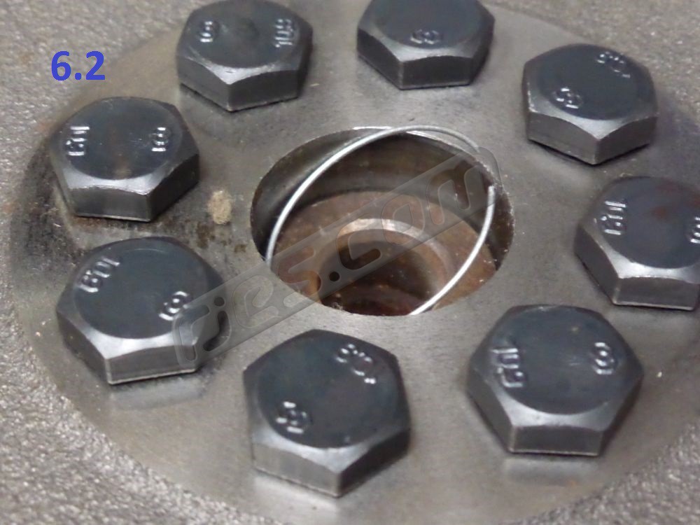
6.2 Pilot bearing wire ring – Fit the wire ring from the bell housing kit into the pilot bearing hole, pushing it all the way in so it sits against the end of the crank if the flywheel has no pilot / spigot bearing in it (or all the way in so it sits against the pilot / spigot bearing from the engine side if you already have the right pilot bearing in your flywheel)
6.3 Install Pilot / spigot bearing – if you are using a genuine Subaru flywheel tap the new pilot bearing from the bell housing kit into the flywheel bore with a suitable drift (be sure to push on the outer race only). A socket of the correct outer diameter works well as a drift.
6.3.1 If you are using any type of aftermarket flywheel, don’t just rely on the fit of the bearing in the flywheel bore to keep the bearing in place (unless you have a suitable bore gauge and have checked that the bore is less than 31.979mm). Some aftermarket flywheels have the bore machined to an incorrect tolerance range. Usually the bearings fit them OK, but sometimes they are too loose.
Thoroughly clean the flywheel bore and the bearing outer race with degreaser, and let any excess evaporate. Bond the bearing into the bore, ideally using a Loctite cylindrical retainer such as Loctite 603 or 638. Run a small bead all around the outer bearing race and the flywheel bore before drifting the bearing into the flywheel.
32mm disc hub maximum diameter 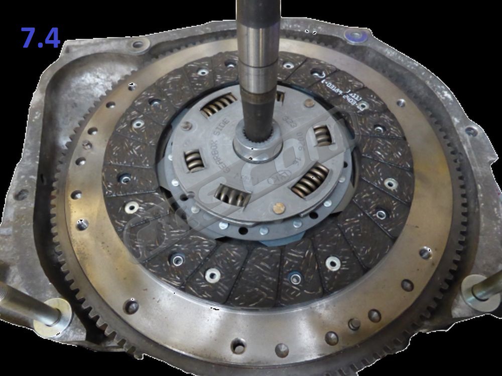
Clutch disc centring 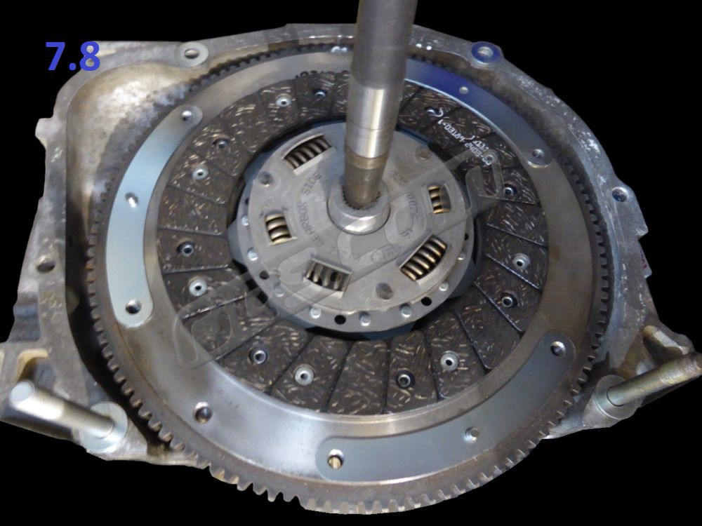
Fit clutch shims if you’re usinga VW clutch disc and they’re included in your bell housing kit 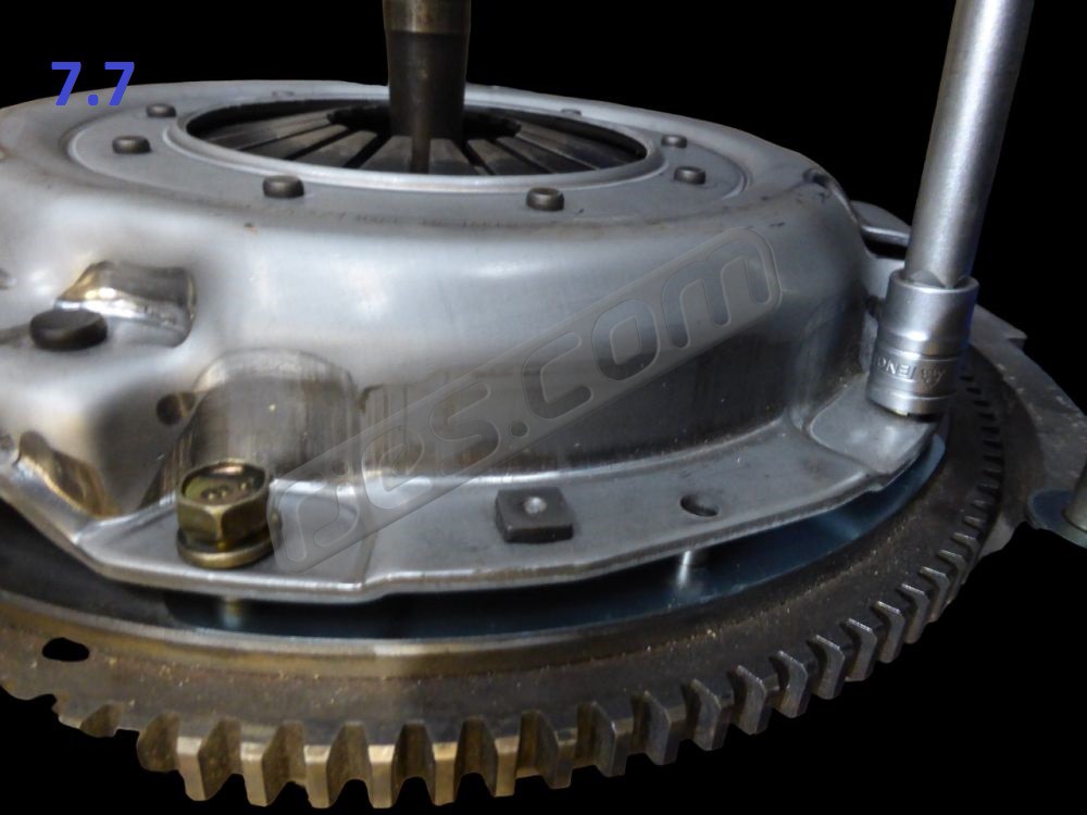
Progressively tighten all the clutch pressure plate bolts. Use Loctite if they don’t have locking washers
The genuine Subaru pressure plate screws have captive locking washers. If you use screws without captive locking washers, either use loose locking washers or Loctite them with a low strength thread lock such as Loctite 238. Remove the clutch alignment tool. The procedure for fitting all types of Subaru Clutch to the flywheel is the same:
7.1 Clean the flywheel friction face of all dust and grease with solvent degreaser on a clean rag. Use brake or carburettor cleaner. Repeat for the pressure plate. New flywheels and clutch pressure plates often have oil on them, and this needs to be removed.
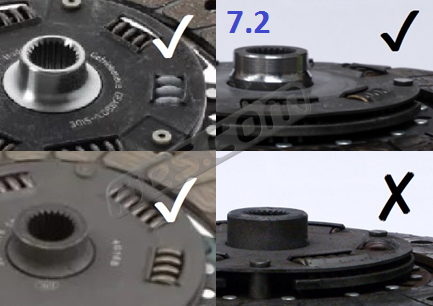
7.2 VERY IMPORTANT – Do not use a VW clutch disc on which the protruding hub on the gearbox side is a bigger diameter then 32mm. No OEM VW discs were larger than 32mm, but LUK changed the design of their aftermarket discs from the design they originally supplied to VW
Upper Left: Sachs 1861 581 435 or 1861 581 437
Lower Left: LUK 323 0076 16 – original design as supplied to VW and into the aftermarket until the mid 2010’s
Upper Right: The discs we stock
Lower Right: LUK 323 0076 16 – mid 2010’s onwards aftermarket design. DO NOT USE THIS DISC Note LUK did not change the part number when they changed the design. This change made no difference in the intended VW applications, but makes the newer design disc unsuitable for use in Subaru engine conversions using our bell housings
7.3 Check the flywheel for scoring, cracks, or discolouration (suggesting overheating), and check that it is not distorted with a straight edge. Replace as necessary. The flywheel friction surfaces crack radially when abused. Repeat for the pressure plate if using a second hand one.
7.4 Using either a clutch centring tool, an input shaft from an old transaxle (as shown in the pic), or a universal centring tool, align the clutch disc with the pilot bearing in the flywheel. Take care to get the disc the right way around (i.e. with the protruding damper hub side (sometimes marked ‘transmission side’, ‘getriebe seite’ or similar) nearest to the transaxle. This is very important.
If you don’t have a centring tool you can wrap tape around a suitable metal bar or wooden dowel in two positions until the one at the end fits inside the pilot bearing, and the one next to it fits inside the disc. You’ll need to be very careful using it though, as it’s obviously not as good as a proper centring tool.
7.5 Check for white paint marks on the flywheel and pressure plate. If both have these marks, they show the imbalance high spots of each, and must be positioned as close to 180 degrees apart as possible. Not all Subaru clutches and flywheels use these marks. Turn the pressure plate as necessary.
7.6 Slide the pressure plate over the centring tool and disc, and temporarily fit one of the M8 pressure plate screw nearest the top of the flywheel to keep it in place.
7.7 If your bell housing kit included three curved shims and you’re using a clutch kit with a VW clutch disc, fit them over the pressure plate dowels and fit all of the remaining M8 screws through both the pressure plate and shims, finger tight.
7.8 Tighten the pressure plate bolts to 17Nm (13 fl lb). Tighten each one turn at a time alternating across the pressure plate to avoid distorting it.
Our bell housing to engine cap screw sets 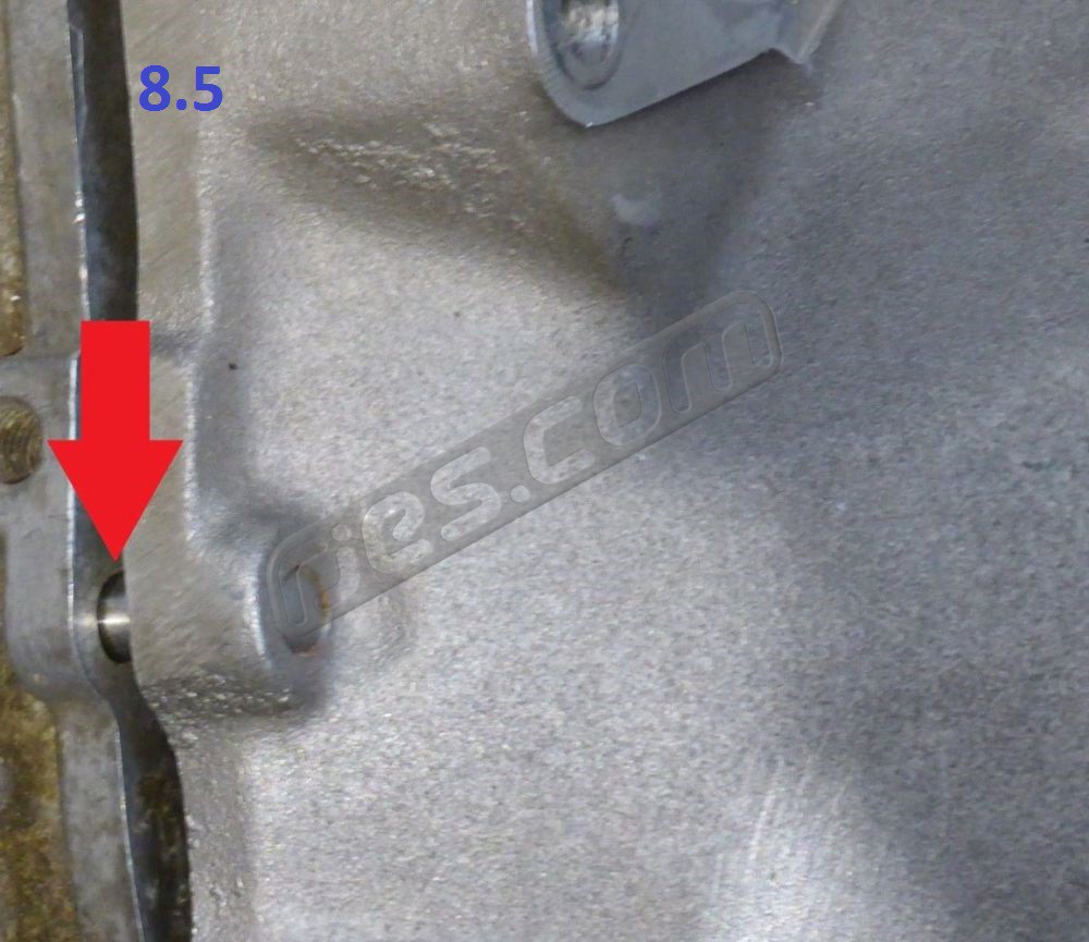
Dowel alignment 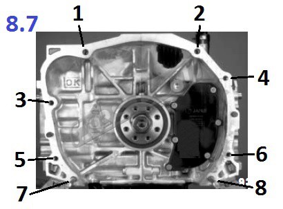
Engine to bell housing fastener locations 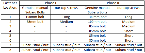
Engine to bell housing bolt length vs location 
Check both bell housing to engine dowels are half in each
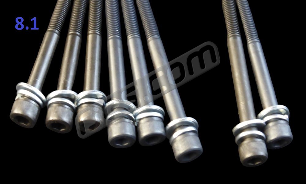
8.1
Bell Housing to engine bolts – if you have the original engine to gearbox fasteners from a manual Subaru, jump to 8.2. If you have an engine from an automatic Subaru, some of your bell housing to engine bolts will be too long. Or maybe you don’t have the original bolts for your manual engine. Our bell housings are designed to use the standard Subaru manual bell housing to engine fasteners. The longer auto bolts can’t be shortened, as they then have almost no thread left. The bolts are not standard parts, and you’ll struggle to find anything suitable from anywhere other than Subaru. The genuine bolts used to be reasonably priced, but are not anymore.
We stock sets of aftermarket bolts which are the correct spec which are much more reasonably priced (but have Allen rather than hex heads), in sets of two for the Phase I engine bell housing bolt pattern, and six for the Phase II pattern. If you have a EZ30 engine they have even more engine to bell housing fasteners, but they’re not necessary – just use the 2 studs and 8 bolts of the Phase II pattern (the heavier EG33 engine only used the 2 stud / 2 bolt Phase I pattern, but the SVX doesn’t have any issues with engine to gearbox attachment).
8.2 Lubricate the input shaft splines with a VERY small amount of general purpose grease. Use the absolute minimum amount, and wipe off any excess.
8.3 Look through the clutch disc centre hole to double check that you definitely did fit the pilot / spigot bearing into the flywheel – yes, we have had multiple customers manage to assemble their conversions without a pilot / spigot bearing. The best case is that this could mean re-doing a lot of work (you’re unlikely to find out until you start the engine). The worst case is that this can do quite a lot of damage if driven.
8.4 Slide the engine and transaxle together in as straight a line as possible, aligning the two Subaru engine studs with the bell housing holes. Avoid bending the clutch pressure plate diaphragm spring with the input shaft by keeping the engine and bell housing faces parallel. Whether you need to join the engine and transaxle before fitting the transaxle into your VW will depend on your VW model (see the workshop manual), and what Subaru engine mounting system you are using. Hoist / prop up the two so you can work around them safely whilst joining the two together, as the workshop manual describes for a VW engine.
8.5 If you are lucky, the engine and gearbox will slide together easily until the two engine to gearbox dowels reach their holes. It is more likely that when the engine and bell housing faces are around 20-30mm apart you will probably find they won’t go any further. If so, the input shaft splines have not aligned with the clutch disc. Rotate the crank very slightly as the two go together with a ratchet on the crank pulley to help the input shaft splines engage with the clutch disc. You’ll probably feel them align, and then be able to slide them together further. They should then slide together easily until the dowels start in their holes with a little wiggling, and almost no force needed once the splines are aligned.
If the engine and gearbox won’t slide together until the dowels reach their holes, don’t force anything, and under no circumstances use the bell housing to engine fasteners to try to pull them together. This is a sign that there is a problem that you need to fix before you can go any further. You can do serious damage by trying force them together (and some customers have). It could be that the clutch disc is not centred accurately enough, or that you have the wrong pilot / spigot bearing in the flywheel.
8.6 Once both engine to gearbox dowels have reached their holes, everything has aligned correctly, and you won’t be able to slide the engine and gearbox any closer together.
Loosely fit the Subaru nuts onto the two lower engine to bell housing studs, but don’t tighten them yet.
8.7 If using either the genuine Subaru manual engine to gearbox fasteners or our aftermarket set on an engine with the Phase I engine to bell housing fastener pattern (i.e. 2 studs, 2 bolts), fit the short bolt in location 2 as shown in image 8.7. Screw it in many turns by hand – they screw directly into the aluminium crank case.
If using the genuine Subaru manual engine to gearbox fasteners or our aftermarket set on an engine with the Phase II engine to bell housing fastener pattern (i.e. 2 studs, 6 bolts), fit the short bolt in location 2 as shown in image 8.7. Screw it in many turns by hand before using any tools – they screw directly into the aluminium crank case
If using our aftermarket manual engine to gearbox fastener set on an engine with the Phase II engine to bell housing fastener pattern (i.e. 2 studs, 6 bolts), fit a medium length bolt in location 2 as shown in image 8.7. Screw it in many turns by hand before using any tools – they screw directly into the aluminium crank case
8.8 Carefully tighten the two nuts and the bolt at location 2 with hand tools one turn at a time before moving to the next fastener. They should need minimal effort. Check that both dowels are going into their holes OK. Continue until the engine and bell housing faces are touching.
8.9 Double check that both engine to bell housing dowels are half in each. If one or both dowels are not half in the engine, half in the bell housing (or are missing) this can cause a lot of damage.
8.10 Fit the Subaru manual starter motor and the rest of the engine / starter to bell housing fasteners. Again, screw then all in many turns by hand before using any tools – they screw directly into the aluminium crank case. If you have an engine with the Phase I engine to bell housing fastener pattern (i.e. 2 studs, 2 bolts), Loctite the stud from the bell housing kit into the tapped lower starter motor hole in the bell housing with.
8.11 Torque all the bell housing bolts to 44 – 54 Nm (34 – 40 fl lb
8.12 If you are using a ‘pull to release’ clutch, you need to latch the release bearing into the pressure plate. Until you do this, pressing the clutch pedal will move the release bearing only, not the clutch. To latch the bearing in to the pressure plate, unhook the slave cylinder pushrod from the ball on the clutch release arm, and push the arm towards the slave cylinder further than it would go with the pushrod in place. You may need to temporarily slide the pushrod out of its rubber gaiter or unbolt the slave cylinder. You will feel the bearing latch into the pressure plate, after which there will be significantly less free play in the movement of the clutch arm. Refit the slave cylinder or pushrod. See section 9, below for how to separate the engine and transaxle with a turbo clutch.
8.13 Fit the Subaru flywheel cover. Every Subaru engine has a flywheel cover, and they always come out of the car with the engine, so cannot get left behind. But they are frequently missing when engines are sold or in customer’s conversions, possibly because they are easily damaged once the engine is out of the Subaru if they are left bolted to the engine. If you’re replacing a Subaru flywheel cover, any of them will do, but some have such a large slot in them that they barely do anything. Others have a large slot which faces backwards in the Subaru, but forwards in a VW so are best avoided. Others have a bolt on section in the middle, for no apparent reason. The best cover to use is one piece, and has a single 7mm hole.
Temporarily move slave cylinder and rotare release arm anti-clockwise while separating engine and gearbox 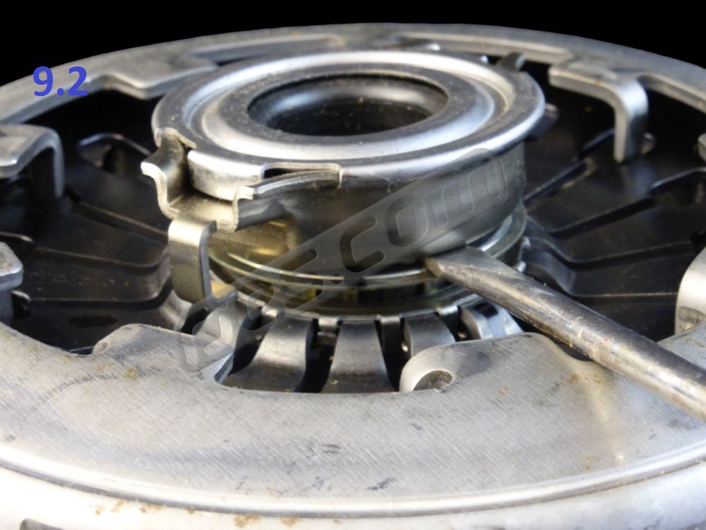
Removing release bearing from ‘pull to release’ pressure plate – twist flat bladed screwdriver
With the ‘pull to release’ clutch as used in all turbo Subaru’s, the release bearing and pressure plate have to be latched together when the engine is installed (see point 7.12). This means that if you undo all the bell housing bolts to separate the engine and transaxle, the two ate still held together by the clutch release mechanism. To separate the engine and transaxle with a ‘pull to release’ clutch, the release bearing must come out with the engine. To allow this, it has to be released from the clutch release mechanism:
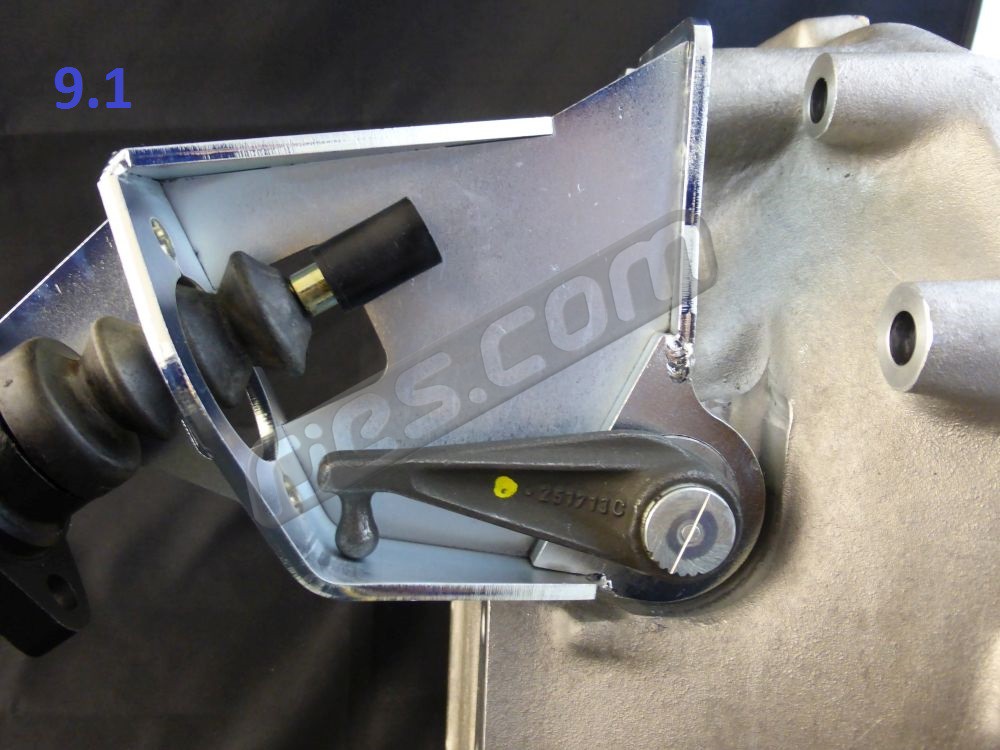
9.1 Temporarily unbolt the slave cylinder from its bracket so it can move about 25mm from the bracket – no need to disturb the hydraulics. This will allow the arm on the clutch release shaft to move way beyond its usual movement range (anticlockwise as viewed looking onto the end of the clutch release shaft from the opposite side of the gearbox to the starter motor).
9.2 Carefully ease the engine and transaxle apart, twisting the clutch release shaft arm back and forth (mostly anticlockwise when viewed a described in 9.1) if necessary until the release bearing is released from the clutch shaft and slides off its guide tube.
9.3 Remove the release bearing from the pressure plate by inserting a flat bladed screw driver and twisting it.