
Vehicle speed sensors for every rear engined VW to Subaru or inline VW engine conversion application
……. (as long as you’re using the original VW speedometer), including the difficult ones such as the 1982 / 83 T25 / T3 / Vanagon:
Price: from £47.50 GBP + VAT (£57.00)
Rear engined air cooled VW models – M18 VSS:
Price: £61.67 GBP + VAT (£74.00)
All air cooled VW models have screw on speedometer cables, and the vehicle speed sensor screws between the speedo and its speedo, so no modification to any VW parts needed. Our sensor is shorter than similar models available elsewhere. Shown here fitted to a bay window bus instrument cluster:
Part no. 800-00064, for Subaru engine conversions
Part no. 800-00065, for VW inline (GTi or TDi, etc) engine conversions. Sometimes also used in early Golf, etc conversions to other VAG engines
Supplied with either 2m of unterminated cable if you’re not using our harness work, or with the relevant connector to plug in to your front extension harness already fitted if you are.
If wiring the sensor in to your engine management (or GPS, cruise control, etc) yourself, the positive supply should be fused to suit the wiring used (typically a 10A or 15A fuse, although the senor only draws a few milliamps).
Note: these models are not protected against reverse polarity, so double check your connections before turning the power on if wiring one up yourself.
T25 / T3 / Vanagon VSS. all 1984 onwards and some 1982 / 1983
Price: £47.50 GBP + VAT (£57.00)
Part no. 800-00018, for Subaru engine conversions
Part no. 800-00066, for VW inline (GTi or TDi, etc) engine conversions. Sometimes also used in Golf, early T4, etc conversions to other VAG engines
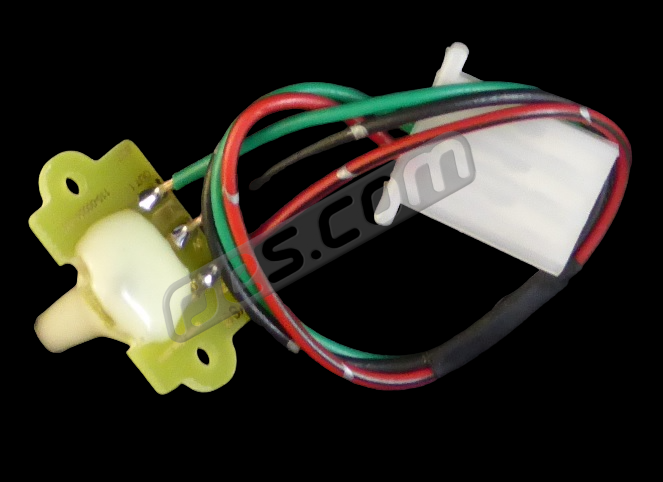
Supplied with the connector fitted as shown, and either with the opposite connector and terminals loose, for you to install if you’re not using our harness work), or with them installed on your front extension harness if you are.
These models are protected against reverse polarity and output overload, making them hard to kill by connecting incorrectly (even if you deliberately try!). If wiring the sensor in to your engine management (or GPS, cruise control, etc) yourself, the positive supply should be fused to suit the wiring used (typically a 10A or 15A fuse, although the senor only draws a few milliamps).
 VSS for all 1984 onwards …..
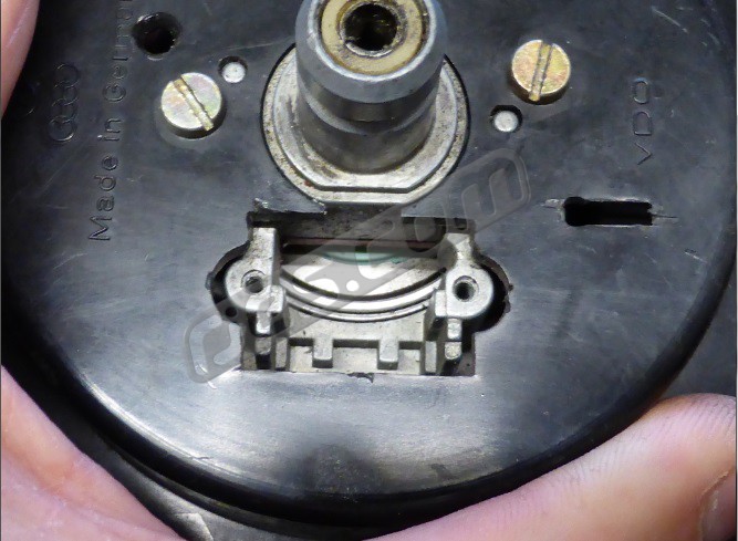 some 1982 / 1983 models only. Speedometer Type B, (recess cover removed)
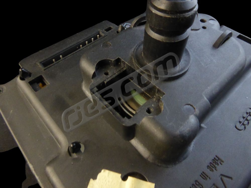 all 1984 onwards models. Speedometer Type C (recess cover removed)
See below for more information on how to identify the different T25 / T3 / Vanagon speedometer types
T25 / T3 / Vanagon VSS. required for some 1982 / 1983 models:
Price: £61.67 GBP + VAT (£74.00)
Part no. 800-00045, for Subaru engine conversions
Part no. 800-00067, for VW inline (GTi or TDi, etc) engine conversions
Supplied with the connector fitted as shown, and either with the opposite connector and terminals loose, for you to install if you’re not using our harness work), or with them installed on your front extension harness if you are.
These models are protected against reverse polarity and output overload, making them hard to kill by connecting incorrectly (even if you deliberately try!). If wiring the sensor in to your engine management (or GPS, cruise control, etc) yourself, the positive supply should be fused to suit the wiring used (typically a 10A or 15A fuse, although the senor only draws a few milliamps).
 Prong type VSS, required for some 1982 / 1983 models…….
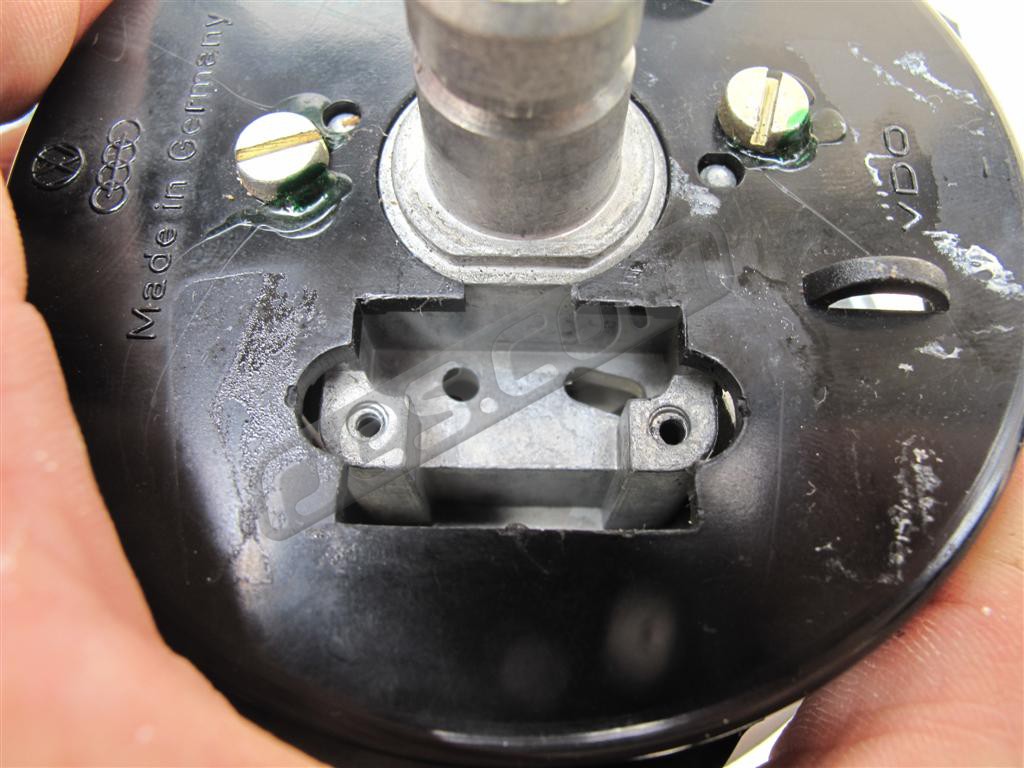 some 1982 / 1983 only. Speedometer Type A (recess cover removed)
See below for more information on how to identify the different T25 / T3 / Vanagon speedometer types
Rear engined water cooled VW models – you need to check which VSS type you need if 1982 or 1983:
The water cooled models use clip on speedo cables, so the screw on speed sensors from air cooled models can’t be used. There are 3 different types. They all have built in speed sensor locations intended for VW’s analogue cruise control sensor, next to where the cable clips on, but do not all use the same sensors:
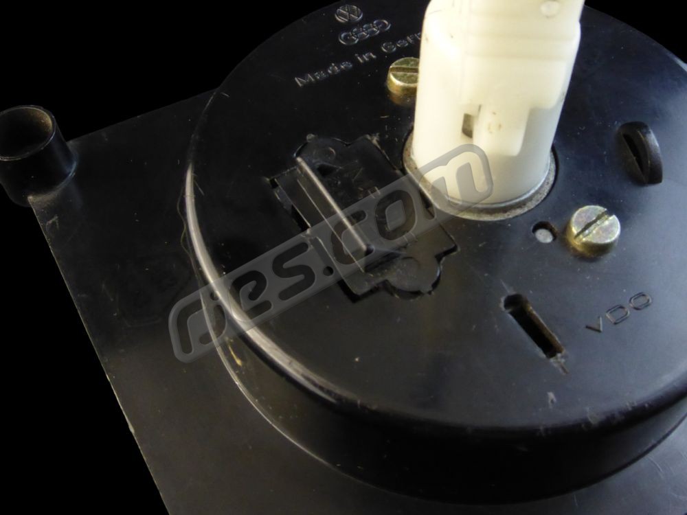 VSS recess cover – next to cable, marked ‘Impuls Geber’ or ‘Abgrif’. Break this away with pliers.
- Water cooled VW T25 / T3 / Vanagon speedometer Type A: Recess cover removed – 1982 / 1983 speedometer
- Water cooled VW T25 / T3 / Vanagon speedometer Type B: Recess cover removed – 1982 / 1983 speedometer
- Water cooled VW T25 / T3 / Vanagon speedometer Type C: Recess cover removed – 1984 onwards speedometer
The sensor recess is covered by a plastic cover moulded into the speedo housing as shown above. This cover is designed to be easily broken away to fit a sensor, and has a tab so it can be gripped with pliers. It’s marked ‘abgrif’ or ‘impuls geber’ depending on the speedo type.
- Which sensor type you need for 1984 models onwards is easy – the speedometers all identical in terms of how the sensors fit (shown as Water cooled VW T25 / T3 / Vanagon speedometer Type C, above).
- For 1982 / 1982 models it is not so straight forward, as there are two designs. Water cooled VW T25 / T3 / Vanagon speedometer Type A, as shown above can only work with a speed sensor with 2 prongs. Water cooled VW T25 / T3 / Vanagon speedometer Type B, as shown above, can work with either the ‘2 prong’ sensor type or the sensor used by all the 1984 –> models – we recommend the latter, as they’re cheaper. The problem is that until you break away the sensor recess cover on the 1982 / 83 models and look inside, you will not know which type you have, as they are externally identical.
All of our speed sensors for the water cooled applications have built in protection against output overload, reverse polarity and over voltage, making them very difficult to damage by incorrect connection even if you deliberately try.
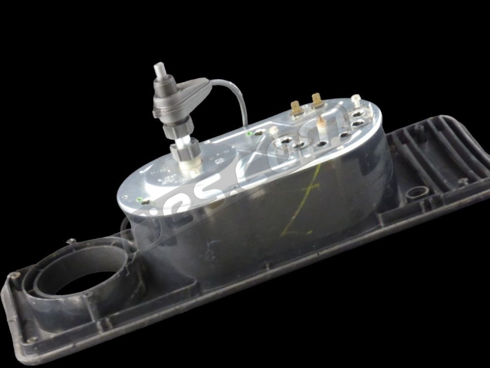
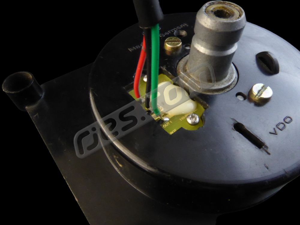 Type A or B T25 / T3 / Vanagon speedo fitted with our VSS
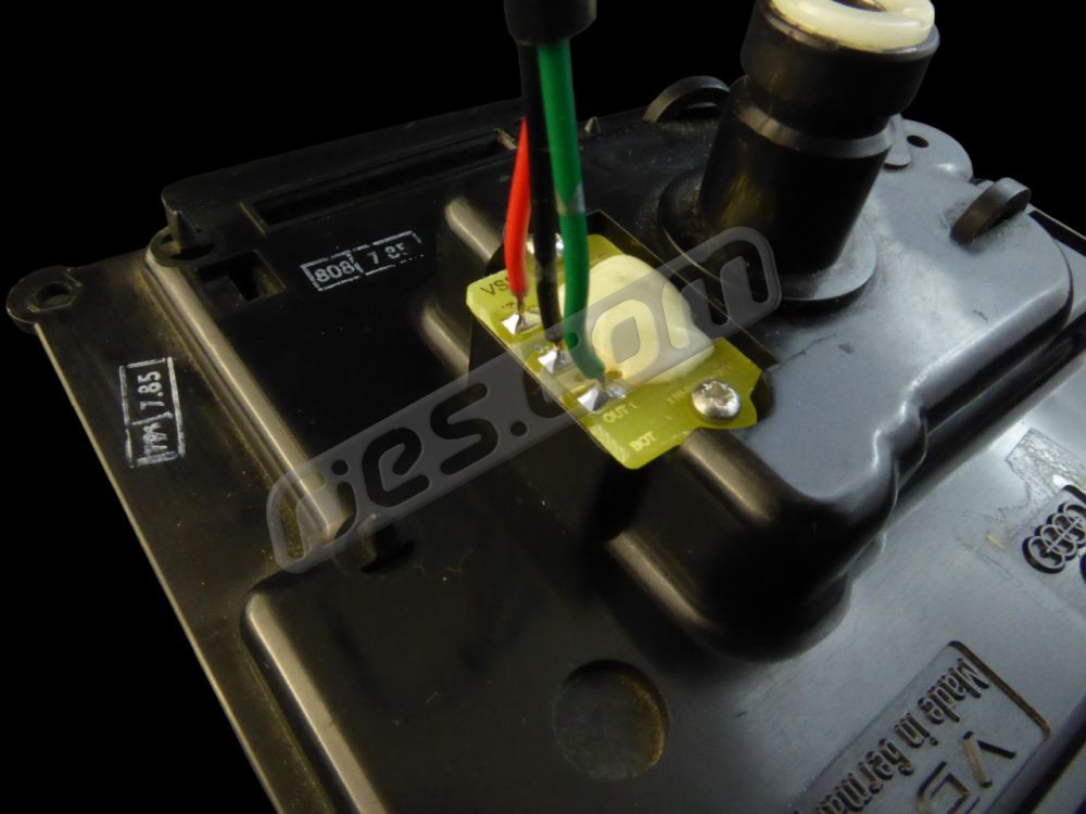 Type C T25 / T3 / Vanagon speedo fitted with our VSS
Speed Sensor Wiring – All Types. ‘Plug and play’ if using our engine management harnesses. Supplied with instructions showing which sensor terminals are which if you are wiring them up yourself.
If the objective is for your engine conversion to run without annoying symptoms and error codes, Subaru engine management requires a vehicle speed input. Many other engines used in conversions also require a speed signal. We also make speed sensors for some of them too – in particular the VW TDi and petrol inline 4 engines (GTi. 1.8, etc), which require a different spec signal to Subaru. In a pre-CAN bus Subaru the signal is created either by the Subaru instrument cluster (–> ~ MY98), or a sensor screwed into the gearbox. The easiest, most reliable source in a VW is to use a sensor which creates the necessary signal from the rotation of either the speedometer cable or speedometer, depending on the VW model. Air cooled VW models did not have any provision designed in for creating a vehicle speed signal, but water cooled models did – it was used for cruise control. These used an analogue speed signal from an inductive sensor which is not compatible with Subaru or the VW inline engine management. They require a digital signal.
We make vehicle speed sensors for every rear engined VW application, including the difficult ones such as the 1982/83 T25 / T3 / Vanagon (cast zinc rather then plastic speedo mechanism with clip on speedo cable). We can even make them for obscure applications such as a water cooled T25/T3/Vanagon model which still need to use the original analogue speed sensor for VW cruise control, but also need a digital signal for the engine management. For some unusual applications we can make special sensors with two independent, different spec outputs. All types just screw into VW parts which you already have (unless you no longer have the original VW dash instruments).