Introduction
Here we cover the history of the the fuel supply system used from the first Bosch electronic fuel injection systems in the 1960’s up to the engine management systems from the early 1990’s. It does not cover the mainly mechanical K Jetronic (CIS) injection systems, although they did have similar electric fuel pump systems. This is because a number of improvements were made before the ideal system was settled on, with the earlier ones not being great.
There is much misunderstanding about how these systems should best be plumbed, and customers regularly get their fuel system plumbing wrong, and have problems as a result even though information on how to do it right has been on out site for over 15 years. Quite a lot of the confusion originates from people basing their system design on what VW and Porsche did with early injected models, or out of date information in workshop manuals for early injected models. The rest comes from incorrect assumptions or online misinformation. This is a much more in depth version. Bosch have published some history on the development of their fuel injection system fuel supply systems, and this is very useful but this seems very much an overview,and some dates in it are definitely wrong. Much more detail can be seen by looking at the pump models and fuel circuit designs in various models as the fuel injection, and later engine management systems developed.
Fuel Pump Types – Bosch Electronic Fuel Injection, 1966 – min 1990’s
1st generation, dismantleable 3 port pumps:
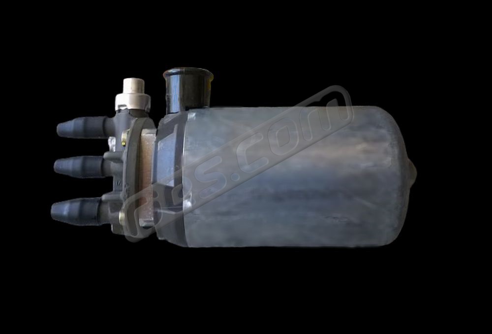
The first Bosch pulsed electronic fuel injection system was Jetronic, which later became known as D-Jetronic – a retronym used to distinguish it from the numerous later Jetronic variants. The ‘D’ stands for Druck (pressure in German), as the fuel metering was based on inlet manifold pressure. The D-Jetronic system was first used in the 1968 VW Type 3 in certain markets. It and all other VW and Porsche D-Jetronic and some early L-Jetronic systems introduced up to about 1974 used Bosch’s first roller cell pump and recirculating fuel system. The pump was based on a design previously used for pumping heating oil, and was developed in 1966.
These pumps had with 3 fuel ports all at one end, and the pumping part was dismantleable, although the motor was not. They used the recirculating petrol injection circuit which became pretty much standard for the next 25+ years, in which more fuel than the engine needed was pumped to the engine, the engine used what it needed with the pressure regulated at the engine depending on inlet manifold pressure, before returning the rest to the fuel tank. However, not all of the flow from the pump was always recirculated via the engine. The pump contained a valve which limited the pressure between the pump output and the fuel pressure regulator on the engine by returning any excess fuel directly to the tank. This was probably a way to protect the pump if the flow around the loop to the engine and back to the tank became blocked somehow – a feature built into the pumps internally in later designs. Fuel returning from the pressure regulator and the return port on the pump combine in a tee piece before flowing back into the (fuel injection specific) fuel tank. The pump motor ran wet (i.e. submerged in fuel), but not much of the fuel flow passed over it.
This system had a number of disadvantages, which are almost certainly why it was short lived, and its eventual successor was very long lived. This system always had an 8mm outlet from the tank, with some models having a fuel strainer inside the tank (914, Type 3, etc), and others not (bay window bus, etc). Both variants always had an inline cellulose filter in a square plastic housing between the tank outlet and the pump suction port, plumbed with 7 or 8mm bore hose to the 8mm pump suction port.
In some models this pump was mounted directly below the tank, and in others, such as some 914 models, were mounted in the engine compartment – a long way away from the tank, which is a very bad idea.
These pumps were also used in various other makes apart from VW and Porsche, and are now sought after by restorers who want everything to be original, and so worth a lot of money in good condition (they’re still available new from Porsche, but cost around 6 times more than the 3rd generation pumps). However, the system they are used in is flawed, and can be improved by updating it to more in line with what was used later if functionality is more important than originality.
Example part numbers:
| Bosch | 0 580 970 001 |
| Porsche | 901 608 105 00, 911 608 107 00, 901 608 105 05 |
| VW | 311 906 091 D |
The inline filter before the pump, the small inlet plumbing diameter and the very long suction pipe from the fuel tank in some installations (e.g. early 914’s) are the biggest problems with the design of the fuel systems that these pumps were used in. All were solved in later models.
2nd generation, dismatleable 2 port pumps
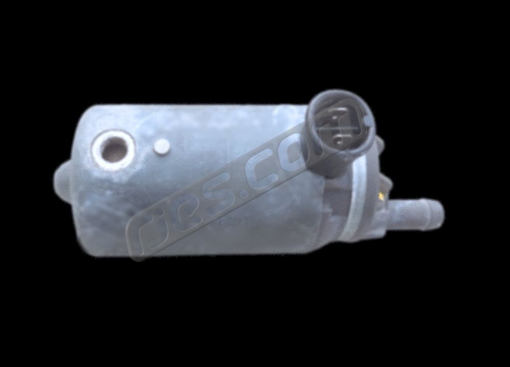
The 2nd generation of roller cell injection fuel pump was a development of the first. It does not seem to have been used in VW models, but was used in certain 1974 and 1975 Porsche 911 models with K-Jetronic (mechanical, continuous) fuel injection. The ‘K’ stands for Konstante (constant in German) – i.e. non pulsed fuel injection, which was a mechanical system. It would not be relevant to the history of electronic fuel injection fuel systems, except it was the first to feature some changes which were significant steps on the way to what because the default fuel injection fuel system design for many years after the mechanical K-Jetronic systems had been superseded. The basic design of this pump is similar to the 1st generation of pumps, with three main differences:
- Return port to the tank was eliminated, so all of the fuel pumped flows around the loop to the engine. They still have a pressure relief valve, but any fuel it vents is internally returned to the inlet, as the 3rd generation pumps do. This considerably simplifies the plumbing.
- The pump inlet diameter was increased from 8mm to 12mm. This is good indication that one of the drivers for this redesign was reducing the sensitivity of roller cell pumps to damage due to cavitating when inlet flow is restricted.
- The pump outlet moved to a radial position at the opposite end of the pump, so all of the flow now passed through the motor.
The 911 models which used this pump also featured some important changes to the fuel system design which are also clearly intended to reduce the chances of the pumps cavitation, and also became very relevant to what became the default fuel injection fuel system design. These were:
- a 12mm tank outlet and hose to the pump
- a mesh suction strainer in the bulk fuel in the tank (i.e. not inline, and not a pleated paper filter)
Like the 1st generation pumps, these were also used by other makes apart from VW and Porsche, are also very sought after for original restorations, and due to the short time they were used. They’re still available new from Porsche, and also cost around 6 times more than the 3rd generation pumps.
| Bosch | 0 580 254 985 |
| Porsche | 911 608 110 01, 911 608 110 06, 911 608 110 56 |
| VW |
Example part numbers: Bosch 0 580 254 985
3rd generation, 2 port, non dismantleable, axial flow pumps
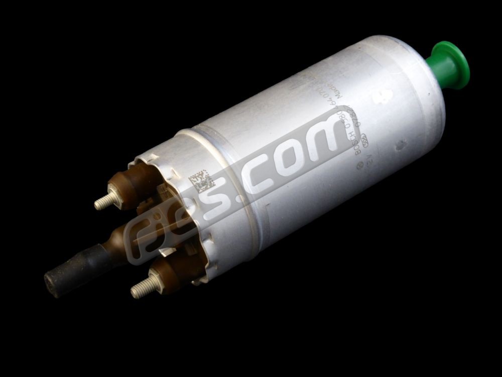
A completely new roller cell pump design was introduced for the L-Jetronic and K-Jetronic injection systems, with some Bosch documentation stating that this was in 1979. However, this is clearly an error, as numerous cars used them starting around 1974 onwards. This design built on the changes made to the 2nd generation by introducing ceramic components inside the pump chamber. This was very likely also to be driven by the desire for longer pump life and increased resistance to cavitation. The first VW / Porsche applications were in models which used Bosch’s then new L-Jetronic fuel injection system. The ‘L’ stands for Luft, air in German – the first electronic fuel injection system to meter fuel based on directly measuring airflow into the engine.
Some L-Jetronic applications such as the 914 continued using the 1st generation pump in 1974, but the 3rd generation pumps seem to have quickly replaced both the 1st and 2nd generation designs in just about all applications after that.
The information which Porsche used to re-design the tank to pump fuel system for the 911’s which used the 2nd generation pump doesn’t seem to have got through to whoever designed the fuel systems for the 4 cylinder Porsches and VW’s (914, 411,412,Bay window / T2b bus). Or it did, but they opted to minimise the changes to the other existing components to accommodate the new pumps instead. Both continued using tanks with 8mm outlets, and an inline paper filter between the tank and pump. At first both just used a new design of filter with an 8mm inlet and a 12mm outlet. This is a major weakness, as it makes the life of the expensive pump very dependent on the regular maintenance of the fuel system. VW and Porsche did however stop mounting the pumps remote from the tank – the 3rd generation pumps are always mounted below the tank, which is a major improvement.
This type of pump, mounted outside the fuel tank quickly became the pump of choice, in almost all subsequent Bosch injection systems and other systems made under licence using Bosch technology (Lucas, most Japanese, etc) until around 1990, when they started being replaced with peripheral flow, or turbine pumps mounted inside fuel tanks. Bosch documentation states that the era of roller cell pumps was over in 1985, when peripheral flow / turbine pumps were introduced but in reality, roller cell pumps remained far more common until at least 1990. Roller cell pumps were used in most European and Japanese cars from the mid ‘70’s to the late ‘80’s or early ‘90’s. Many of these pumps are also the correct specification for many much later fuel injection systems used on engines which had in tank pumps. This makes them ideal when transplanting later engines into older models never intended to have in tank pumps. However, Bosch and / or their early OEM customers didn’t settle on the optimum design of the fuel system plumbing fuel system using these pumps until they had been in use for a few years – around the very early 1980’s. This means many of the earliest OEM applications of roller cell pumps including all the VW rear / mid engined applications on models introduced before the late 1970’s are not ideal. They can easily be improved in many of these VW applications.
Example part numbers: Because this type of pump was so widely used, in so many different cars, there were originally hundreds of different part numbers. Many were near identical spec to others in terms of their output pressure and flow rats, with the differences being to do with the mechanical installation – different fuel inlet and / or outlet, and / or different electrical terminal types, etc.
As the OEM applications for the 3rd generation pumps ended in the early 1990’s, as all manufacturers switched to in tank fuel pumps, Bosch rationalised the huge range of standard replacement 3rd generation pumps down to 72, as so many had near identical specs. Then later, as the OEM applications stopped being supported by many OEM’s (as the original applications passed 10 years old – the required minimum, or 15 years old as used by VW), Bosch rationalised their range much more, down to just 7 pumps in some markets such as Australia. The also moved the production of the pumps from Germany to the Czech Republic in around 2009.
Bosch Standard Aftermarket External 3rd Generation Fuel Pump Specifications
5 bar pump models typically intended for K-Jetronic continuous (mechanical) injection
4 bar pump models typically intended for forced induction pulsed / electronic injection
2.5 and 3 bar pumps typically intended for normally aspirated pulsed / electronic injection
Bosch 3rd Generation Roller Cell Fuel Pump Part Numbers and Specifications:
| Genuine Bosch Aftermarket External Fuel Pump Part Number: | Delivery @ normal voltage | System Pressure | Normal Voltage | Current | Pressure Limit | Total Length | Pump Diameter | Pressure Connection Thread | Pressure Connection Diameter | Additional Fittings | Electrical Terminals |
| l/h: | Bar(psi): | V: | A: | Bar: | mm: | mm: | mm: | ||||
| 0 580 254 053 | 175 – 228 | 5 (73.5) | 13 | < 11.4 | 8 – 14.5 | 180 | 60 | M12 x 1.5 | – | – | + M4, – M5 |
| 0 580 254 909 | 148 – 198 | 5 (73.5) | 13 | < 8.7 | 8 – 14.5 | 180 | 60 | M12 x 1.5 | – | – | + M4, – M5 |
| 0 580 254 910 | 130 – 200 | 5 (73.5) | 13 | < 9.8 | 8 – 14.5 | 203 | 60 | M12 x 1.5 | – | – | + M4, – M5 |
| 0 580 254 911 | 95 – 135 | 4 (59) | 12 | < 5.2 | 6.5 – 8.5 | 199 | 52 | M12 x 1.5 | – | M10 x 1.0 | + M4, – M5 |
| 0 580 464 069 | 98 – 148 | 4 (59) | 12 | < 7.0 | 4.8 – 8.5 | 186 | 52 | M12 x 1.5 | – | M14 x 1.5 | + M4, – M5 |
| 0 580 464 070 * | 130 – 195 | 3 (44) | 12 | < 6.5 | 4.5 – 8 | 175 | 52 | – | 8 | – | + M4, – M5 |
| 0 580 464 085** | 95 – 145 | 2.5 (37) | 12 | < 4.5 | 4.8 – 8.5 | 175 | 52 | – | 8 | – | + M4, – M5 |
**0580 454 085 is the Bosch pump specified for all the electronically injected rear engined VW models (i.e. L Jetronic, Digijet, Digifant I). It has a 2.5 bar system pressure, which in theory makes it unsuitatble for the 3 bar systems used on normally aspirated injected Subaru models. However, an awful lot of VW conversions use the original VW pump, and we have never known this cause any kind of problem. They produce enough flow at 3 bar to keep the engines happy. If you’re buying a Bosch roller cell pump for a Subaru conversion though, the right pump to buy is 0 580 464 070.
Which Bosch Fuel Pump should I buy for my VW Subaru Engine Conversion?
Normally aspirated: 0 580 464 070
Turbo: The standard pump for a Ford Sierra or Escort Cosworth has successfully been used in turbo Subaru conversion applications, Bosch part number 0 580 254 941, superseded by 0 580 464 205. Check whether it suits your application first though, especially if you have higher than standard boost pressure.
How Bosch Roller Cell Fuel Pumps Work:
Roller cell pumps are a positive displacement type pumps. They effectively move a fixed amount of fluid from one side of the pump to the other per revolution. Because stopping the flow from a positive displacement pump can create very high pressures – high enough to damage the pumps or other components, they have a pressure limiting valve built in. This never operates under any normal conditions, and the pressure that they operate at is the ‘Pressure Limit’ in the table of Bosch data above. The ‘Pressure Limit’ has nothing to do with the pressure that the fuel system runs at. To suit different applications, the pumps are made for a few different system pressure ranges, with the exact pressure that the system runs at being determined by the fuel pressure regulator on the engine, not the pump.
Roller cell pumps for normally aspirated applications are generally designed for either 2.5 bar / 37 psi, or 3 bar / 45 psi system pressure injection systems, as these effectively became standards, no doubt helped by the fact that most fuel injection and engine management systems that they were used in were either Bosch, or made under license from Bosch. This system pressure is the pressure as measured anywhere between the fuel pump outlet and the fuel pressure regulator, with the vacuum hose to the pressure regulator disconnected.
Models for standard turbo applications will typically show the same system pressures when measured with the regulator vacuum hose disconnected, however, they don’t use the same pumps. On a forced induction engine the pump must also be able to overcome the boost pressure, so under boost the actual fuel pressure will be system pressure + boost pressure. As production cars don’t generally use more than 1 bar of boost, a typical production turbo fuel pump will be generally be rated to provide suitable flow rates at around 4 bar / 49 psi. Higher boost pressures typically used in aftermarket tuned engines or very high powered production models require higher pressure pumps.
Higher pressure pumps were also used for the K Jetronic (CIS) mechanical injection system.
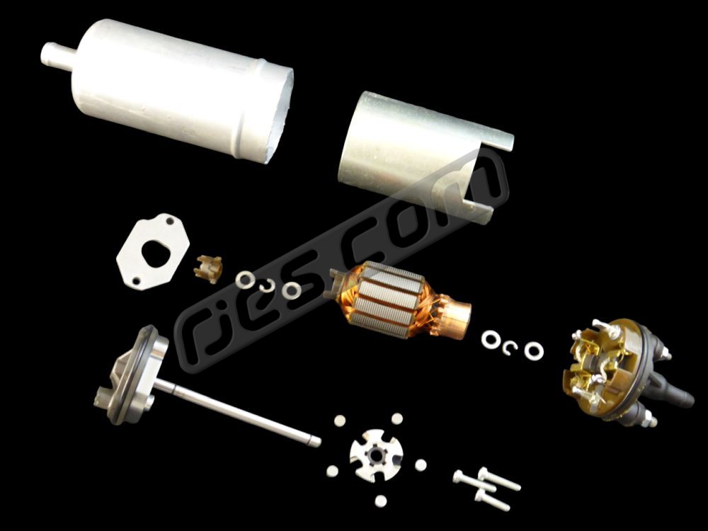 Exploded view
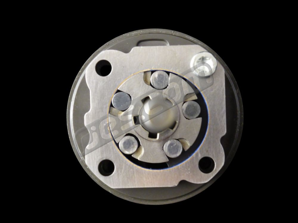 Roller Cell
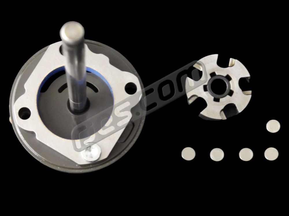 Roller Cell dismantled
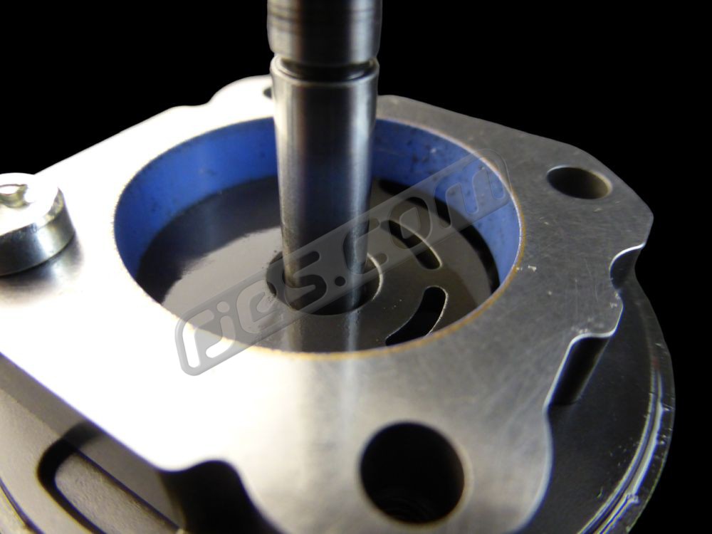 Inlet ports and debris which killed this pump
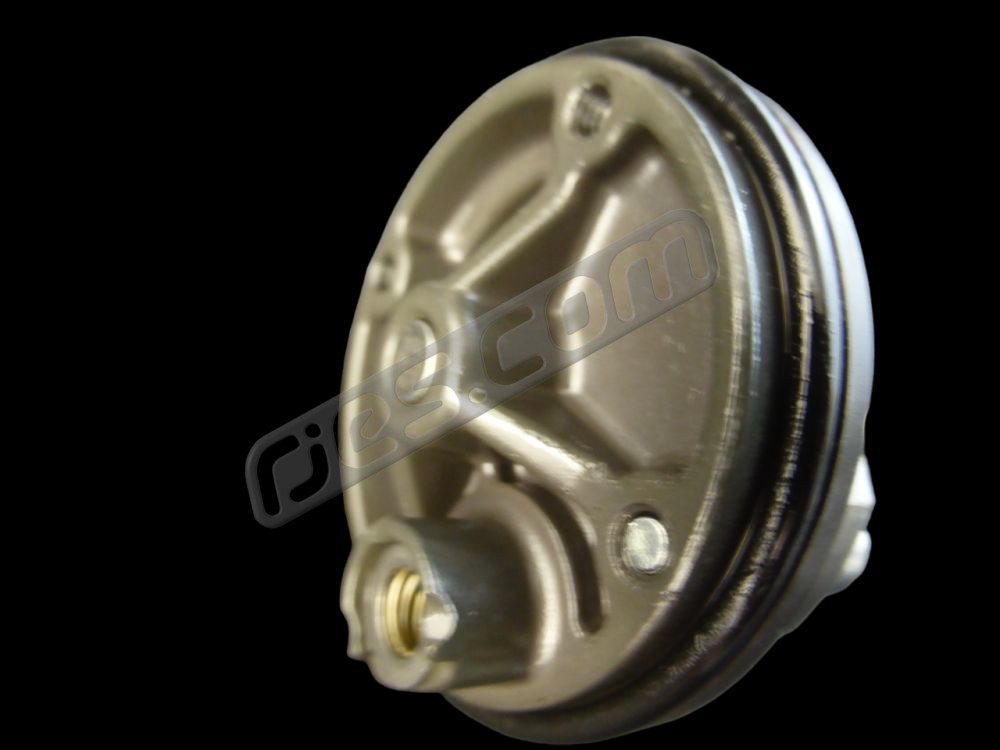 Pressure relief valve
- 4ht Generation, In-Tank, Peripheral Flow / Turbine Pumps
The 4th generation of fuel injection fuel pumps were introduced in 1985, and were a peripheral flow, or turbine type pump. The likely driver for this change is that they have far fewer moving parts, so will be cheaper to manufacture, and possibly more reliable. However, as a roller cell pump in a well designed system can last far longer than the OEM’s would ever require, better pump reliability is not likely to have been a major requirement. This coincided with the start of mounting fuel pumps inside fuel tanks, which offers a number of advantages:
- Further reduction in the chance of pump cavitation by reducing the suction distance to almost nothing
- Noise reduction
- Better pump cooling
- Much simpler and cheaper installation of the perfect suction strainer before the pump
- Cheaper / easier assembly, as the pump is typically mounted in a pre-assembled module containing other parts such as the suction strainer, level sender, electrical connector and fuel outlet and return fittings, etc
It is likely that the introducing of the 4th generation of pump coinciding with pumps being moved to inside the fuel tank is not a dependency, as many (but not all) in-tank pumps can also be used in external applications.
In aftermarket engine conversion applications, most of the engines being used will come from newer applications than the vehicles which they are going into, so would originally have used in-tank peripheral / turbine pumps. Fortunately the spec of the rest of the fuel systems remained the same for many more years (typically until at least the mid 2000’s), so external pumps can easily be used in older vehicles fitted with newer engines, which can simplify installing a newer spec fuel system in an older vehicle a lot. The details of how this is best done are critical though, very widely misunderstood, and so very frequently got wrong.
Roller cell fuel pump reliability and cavitation
The 3rd generation roller cell fuel pumps are extremely reliable when used correctly, regularly lasting well over 100,000 miles or even 30+ years. However, they’re also very sensitive to having their fuel inlet flow restricted. This is not a pump quality issue – it is inherent to this type of pump, regardless of quality, and is why the 2nd generation onwards have a much larger diameter inlet (typically 12mm) than outlet (typically 8mm). Restricting the inlet flow causes the pump to cavitate, and the cavitation erodes away the ceramic roller cell pump housing, massively accelerating the pump wear rate. The housing eventually becomes so rough that the rollers can no longer roll across it, and the pump jams. This either stalls the motor causing the fuel pump fuse to blow, or it shears the plastic coupling between the pump and motor, leaving the motor spinning and sounding fairly normal, but pumping no fuel.
Cavitation is the most common failure mode for these pumps in non-standard installations by far (and almost certainly also in OEM applications on old vehicles), and it can have many causes. The failed pump is never the cause of the problem if it has been cavitating. It is only a symptom, meaning if you just replace the pump without fixing the cause of the cavitation too, the replacement pump will soon die too. This is very widely misunderstood, and very commonly leads those trying to fix the problem who do not have sufficient understanding to do things which make the problem worse (i.e. a vicious circle, or positive feedback), therefore killing their replacement pump even faster.
Roller cell fuel pumps mounted outside the fuel tank make a distinct sound which anyone very familiar with this type of fuel system or very familiar with injected European cars from the mid ‘70’s to the early ‘90’s will probably be able to pick out easily. However, these pumps also have a distinctly different sound when cavitating. It’s subtle – an extra sound which sounds a bit like what you’d think the pump would sound like if it were partially sucking air as you run out of fuel, on top of the usual motor sound from the pump. It happens regardless of fuel level in the tank, so is not actually the pump sucking air. Anyone not familiar with this type of fuel system could probably miss the distinct cavitation sound though – especially if they have a non OEM installation with the pump mounted incorrectly.
The sound of a pump cavitating can also sometimes be confused for sound transmitted into the bodywork by insufficient rubber mounting (especially in aftermarket installations). This video shows a new pump in an ideal spec fuel system (our test fuel supply system, which has a strainer insider the tank and an injection filter after the pump), with the pump running normally and being forced to cavitate by partially closing the valve, which restricts inlet flow), both with and without sufficient rubber mounting (the pump is mounted correctly, but by bending the rubber mounts, the pump body can be made to touch the bracket and transmit noise exactly as they can into vehicle bodies. Note the subtle difference between the sound of cavitation and the sound of insufficient rubber mounting without cavitating:
What is so bad about the way VW and Porsche installed the 1st, 2nd and earliest 3rd generation roller cell fuel pumps for 4 cylinder applications?
Roller cell fuel pumps are very susceptible to damage via cavitation if their inlet flow gets restricted, yet many features of these early installations significalntly increased the chances of this happening:
- Small bore or otherwise unsuitable plumbing and fittings between the tank and pump
- Too much length of plumbing between the tank and pump in some models (particularly the 914’s with the injection pump in the engine compartment)
- Attempting to filter the fuel using inline pleated paper filters to protect the pump from debris in the tank (all air cooled injection models). This is especially bad, and in our opinion the biggest problem because debris is free to flow out of the rank and collect in the small pre-pump filter. It is then trapped there, and quickly clogs the filter, and so require regular replacement. A well designed in tank strainer will never clog due to debris in the tank
- ….sometimes most of the above together, (pre 1975 4 cylinder 914s).
It does look like Bosch nor their OEM customers understood this well initially, but by the time the 2nd generation pump design was introduced in 1974, at least Bosch and Porsche did, as they solved all of the above in the 6 cylinder K-Jetronic 911. However, many VW models – all injected bay window / T2b’s and the air cooled T25 / T3 / Vanagon models with L-Jetronic or models using VW engines such as the 914 were still using compromised fuel circuit designs – they stepped the new 12mm pump inlet back down to 8mm, and continued using pre-pump filters until around 1982. After this they made the same changes that Porsche did with the 2nd generation pump in the 6 cylinder K Jetronic 911’s 8 years before, finally having the system design that was used in pretty much all cars with Bosch injection or engine management for the next 10+ years.
These are all ‘errors’ in fuel system design which are also common in aftermarket engine conversions where an injection system is installed in a vehicle which didn’t originally have one, and this is not entirely a coincidence. Many putting more modern engines into older vehicles already have workshop manuals and parts catalogues which show how the injection fuel systems were originally plumbed. In many cases if you delve into the lists of parts in the catalogue, you can see that the parts for the early systems are all obsolete, superseded at some point by the later systems which were better designs.
Some or even all of the above together make for a very compromised fuel system, which is far more dependent on regular maintenance than it could be.
What did VW, Porsche and just about all other OEM’s do later to come up with the ideal roller cell fuel pump installation?
By about 1983 (VW) and 1974 (Porsche) used fuel systems which do not increase the chances of pumps dying prematurely due to cavitation, both using pretty much the same system for every model (along with almost all other OEM installations from the same era) until in tank fuel pumps took over. This system with all the earlier problems ironed out consisted of:
- An in tank strainer with a large area of mesh (typically around 100 microns) which is not all at the very bottom of the tank (so debris in the tank can never totally cover the strainer in the tank)
- 12mm outer diameter tank outlet pipe, or 9 – 10mm bore fittings, including any plumbing inside the tank
- 11 – 12mm bore hose between the tank and pump
- The pump mounted very near the tank (typically less than 0.5m away), as close to the bottom of the tank as possible or below it
- 6 – 8mm bore rigid tube and hoses forming the plumbing between the pump and engine
- A 10 micron paper filter designed to withstand the system pressure (i.e. a metal cased fuel injection filter) fitted between the pump and engine
- 6 – 8mm bore rigid tubes and hose forming the plumbing between the fuel return line from the fuel pressure regulator back to the tank
When all of the above is correct, this system is very capable of lasting for very high mileages, even if it does not get any maintenance.
If you are installing an injected engine into a vehicle which didn’t originally have one, this is the ideal system that you should fit if you want to get it right 1st time.
Which VW fuel tanks / fuel tank outlets are suitable for fuel injection?
If you want a totally standard spec VW fuel system which is ideal for fuel injection, the only ones are the injected Syncro and 2wd T25 / T3 / Vanagon models later then about 1981. All of the others, including the ones used with OEM fuel injection are either not suitable, or leave room for improvement. Rear engined VW fuel tanks intended for carburetor or diesel typically had 6mm or 8mm OD outlet. The 6mm outlets are not suitable for fuel injection at all, and the 8mm outlets ate not ideal. Which were in what VW models is explained below:
Beetle and Split screen buses: Most of the tanks in Beetles and Split screen busses which do not have a reserve fuel tap instead of a fuel gauge have removable outlet fitting, held in place with a 22mm aluminium nut screwed on to the M18 thread on the tank. These all have 6mm outlets as standard which can be replaced by larger aftermarket outlets. All of the models with this system which were built outside South America has a bronze gauze strainer in the tank
plus and carburetor engined Bay window buses
How to add a fuel return to a VW fuel system which did not originally have one
Troubleshooting Aftermarket or pre 1982 OEM VW or (4 Cylinder) Porsche Fuel Injection Fuel Systems:
How do I know if my fuel pump is cavitating? It is easy to spot cavitation by listening to the pump, but only when you know what cavitation sounds like. See the video above for an example, where we deliberately make a new Bosch pump in an ideal fuel system cavitate by restricting its inlet flow, and also demonstrate other pump noise so you can hopefully hear the difference.
The following is a more detailed explanation of each of the above causes of cavitation, plus other aftermarket engine conversion specific errors in fuel system design which we have seen cause premature pump death due to cavitation, with the most common first:
1. Fitting an unsuitable fuel filter between the tank and the pump. Any inline filter between the tank and the pump is a bad idea. Yes, that’s what VW and Porsche did in early applications, but they abandoned it with good reason. Most filters not designed specifically for the application create too big a fuel pressure drop when fitted between the tank and pump, if not when new, then certainly when they are overdue being changed. This includes all filters intended for carburetor applications and typical metal cased injection filters which are designed to go between the pump and engine. This is because they use pleated paper filter material which catches pretty much all debris, restricting flow and creating a bigger pressure drop the longer between filter changes. The earliest VW roller cell pump installations used small filter, which had to have a short service interval (10,000 or 12,000 miles). Some early Porsche 911’s used a very large filter, presumably to increase the service interval. However, with the consequence of not changing either soon enough being a dead pump.
It is totally understandably why someone unfamiliar with roller cell fuel injection systems would fit a filter before the pump. The filters they are most likely to be familiar with are unlikely to be suitable, and if they have just had a pump die without understanding why, putting a filter before its replacement may seem logical. *
2. Too small a diameter of pipe before the pump, either in the tank or between the tank and the pump). Tanks with brazed in 6mm OD outlets are not suitable at all – they cannot flow enough fuel to prevent the pump cavitating. Tanks with a short length 8mm outlet pipe, either brazed in or screwed in are not ideal, but can work OK as long as all other aspects of the fuel system are correct, and the plumbing steps up to 12mm as soon as possible after leaving the tank*
3. Too long a length of pipe between the tank and pump. Look at all OEM installations introduced after about 1977 which used external pumps, and they are always mounted very near the tank. A customer mounted the pump in the engine compartment, around 3m away from the tank in a 2WD T25/T3/Vanagon. All other aspects of his pump installation seemed correct. The drag in such a long length of hose alone can kill the pump. Also, the correct 12mm hose is far more expensive than 8mm, so fitting the pump close to the tank costs less*
4. Too much debris in the tank of an old, but otherwise perfect specification fuel system with a strainer inside the tank (including the OEM T25/T3/Vanagon fuel system). This is very common when a very old tank originally used for a carburetor or diesel application is re-purposed for fuel injection. Because the only flow out of a carburetor or diesel tank is what the engine uses, they can withstand an enormous amount of debris in the tank, restricting the suction strainer, but still flow the tiny amount of fuel required. They cannot flow the far higher amount of fuel required for fuel injection, so the pump cavitates. There is a very easy test for this if you think it is happening. Wait for the pump to get noisy (i.e. cavitate) when you have a half full fuel tank. Then either brake hard or swerve side to side. The pump will quieten again if you have this problem, as the sudden motion of the fuel in the tank will temporarily wash the debris away from the suction strainer. As you continue to drive normally, the pump noise will slowly come back, as the debris clogs the strainer again.*
5. Installing the pump too high up relative to the tank. This would be difficult to do in some VW models, and is not common, but the pump should always be at, as close to as is possible, or below the height of the minimum fuel level *
6. Unsuitable VW in tank fuel strainer. South American spec carburetor plastic strainers were mostly solid plastic, with just two tiny windows of mesh. These are absolutely not compatible with fuel injection. They cannot flow anywhere near enough fuel, and will cause your pump to cavitate. Our flow testing shoed they restrict the flow when used with a 12mm outer diameter tank outlet fitting by 24%. These were distributed into the aftermarket worldwide. You need the bronze mesh ‘sock’ type strainer, which only reduced flow from the tank by about 10% in out tests.
7. Too many non free-flowing fuel fittings between the tank and the pump. This is typically in racecars, with the tank to pump plumbing made up from lots of money’s worth of anodised aluminium / braided hose fitting, not necessarily over a long distance. Two customers have had this happen, and neither would believe that this was the cause until we persuaded them to temporarily connect the feed to the pump via a 12mm ID hose to a clean can of fuel, and see whether that stops the pump cavitation noise. It did in both cases*
8. Genuine fuel tanks are no longer available for many of the VW applications, so you’re forced to use aftermarket if the original is beyond repair. With some, as long as they fit and don’t leak, they can’t really go wrong because they’re very simple. With others, the internal design of the original part was very complex (e.g. the injected 2wd T25 / T3 / Vanagon), and the aftermarket manufacturers replace the original internal design with something far cheaper to make, and with less quality control. The simplified design does not seem to cause problems, however, the worse quality control can. One customer had a new injection spec tank, the same one which many others have used without problems, but killed 5 genuine Bosch pumps before getting in touch to ask if we could help. Every detail of his fuel system installation seemed correct, and it turned out that there was a flow restriction internal to the tank causing his pump to cavitate, and killing the pumps*
*causes which we have seen kill pumps in customers engine conversions
Non Genuine Bosch Roller Cell Pumps
The 1st and 2nd generation of Bosch roller cell fuel pumps don’t seem to have been copied by any aftermarket manufacturers. This makes sense, as their use was a lot less widespread, and dated from an era when aftermarket copies of any parts were a lot less common. This changes with the 3rd generation of roller cell pump. With them being used so very widely, and into an era where aftermarket copies became common, a huge number of non genuine versions of them are available. There are a couple of makes which are known companies and OEM’s to many other makes such as Lucas and Peirburg which are probably of very nice quality. Other good quality OEM’s who also make aftermarket parts such as Walbro will definitely make good quality pumps of equivalent specs, but which are not directly interchangeable.
However, there is a very large number of companies (mainly in China) making unbranded copies of the 3rd generation pumps. They are very cheap, starting from around 15% of the price of a genuine Bosch pump here in the UK in 2022. They often tend to be louder than genuine Bosch pumps, but some customers have put high mileages on them. If you want to take a chance on them, buy two at that price and keep a spare in the tools to fit it in the vehicle.
Fuel System FAQ:
© R Jones, R J Engineered Solutions Ltd, 2022
References:
How to Understand and Modify Bosch Fuel Injection and Engine Management, Charles O. Probst, ISBN 0-8376-0300-5
Porsche 911 1965 – 1981 Haynes Owners Workshop Manual ISBN 0 85696 691 6
VW 1500 and 1600 Type 3 1963 – 1973 Haynes Owners Workshop Manual ISBN 0 900550 84 8
Numerous Porsche and VW parts catalogues
Electric Fuel Pumps 2009, Bosch 1 987 AP2 076/200808
