
Introduction
Those unfamiliar may assume that the way to cool a Subaru engine installed in a VW would be to use exactly the same cooling system as in the Subaru. However, in almost all cases this is either not practical or not the right approach, for a number of reasons. There are number of fundamental differences when the Subaru engine is installed in the typical rear engined VW application which affect the cooling system design:
- All locations in which the radiator can cool adequately (i.e. relying an airflow from vehicle movement, not fans) under all normal running conditions, in all normal VW conversions, are remote from the engine. This requires often considerably more pipe length, so a larger volume of coolant.
- The standard VW heater / heaters (some models had two) in the water cooled models are not compatible with the Subaru cooling system.
- The desire for a ‘stealth’ cooling system by most owners of originally air cooled VW models means that the cooling system is by definition a compromise. Not in terms of performance when designed correctly, but in terms of the location, orientation and size of some of the components required to achieve that performance, due to their compromised locations.
Solving all of these involves making changes to the system design, slightly altering it from being exactly from being exactly the same as in the Subaru.
Are you a user of Subaru cooling system products from one of our competitors, and have found yourself here because you are having cooling problems? If so, good – the idea is that you can read this yourself rather than phone and ask questions. Also, hopefully it’ll make you question why your supplier almost certainly doesn’t five away this level of detail (there is almost 8000 words plus diagrams here about Subaru powered VW cooling systems, all copyright R J Engineered Solutions Ltd – sorry you do not have permission to copy it), and question why. Could it be that their attention to detail or level of understanding of the systems they work on is lacking?
How the Subaru Cooling System Works in a Subaru
All Subaru EJ, EG and EZ series engines use similar cooling systems. From MY90 to about MY03, the normally aspirated models in particular use an extremely neat, simple system. When compared to the cooling system in the rear engine water cooled VW’s (in particular the petrol ones), and most subsequent VW models, the Subaru system is so much simpler. The Subaru thermostat is a simple single valve type, actuated by a wax capsule or ‘wax motor’ heated by the engine coolant, which throttles flow of coolant from the radiator to the water pump. When the engine has just started from cold, the thermostat is closed, so no coolant flows through the radiator, but an alternative route for the coolant is required, because the pump is running. The alternative route in many cars is also controlled by a second valve controlled by the thermostat, but not in Subarus. The alternative route is the bypass flow, and in Subaru engines the bypass flow mostly passes through the heater matrix. This is explained in more detail below:
Starting (most of) the EJ Series Engines from cold:
When an engine starts from cold, the cooling systems of most car models designed in the era of the EJ and EG series Subarus has 3 jobs to do, with the most important first
- Ensure the engine warms up evenly
- Ensure the engine warms up fast
- Ensure the heater can heat the passenger compartment fast
At the time the balance of priority between 2 and 3 was debatable, and manufacturers would compromise 2 slightly to achieve 3 if necessary.
When an engine with this type of cooling system is cold, almost no flow passes through the radiator. This enables the engine to warm up quickly, which is essential for wear prevention and efficient running. However, flow from the pressure / outlet side to the suction / inlet side of the pump is still required to ensure the engine warms up evenly, and to prevent the pump, which always rotates with the engine stalling (i.e. effectively trying to pump coolant into a blocked pipe). This requires bypass flow, which is effectively a short circuit around the blocked flow through the closed thermostat, to let coolant from the pressure / outlet side back to the suction / inlet. The bypass flow also has another essential job in the EJ series engines – it is what keeps the wax capsule in the thermostat at the same temperature as the engine during warm up. This is achieved by directing the bypass flow directly at the thermostat’s wax capsule.
Many cars control the amount of bypass flow using a thermostat which controls two valves. As the valve controlling flow to the radiator opens because the engine is warming up, the valve controlling bypass flow closes, as the bypass flow is not needed once the thermostat has opened. In this system, the thermostat and its housing are designed in a way which allows the thermostat wax capsule to be heater by the bypass flow when cold, or the radiator flow when up to operating temperature.
Subaru do not use this thermostat controlled bypass flow system. Most models from MY90 to about MY04 use a constant amount of bypass flow under all operating conditions, and this flow is almost all routed via the heater matrix (a tiny amount also flows via the throttle body / idle speed control valve circuit too) at all times. This means that the heater matrix always warms up at the same rate as the engine, regardless of whether the heater is being used or not. Relying on the return flow from the heater to heat the thermostat wax capsule when the engine is cold is an unusual design. It works perfectly in Subarus and almost all VW engine conversion applications (see Subaru Powered VW’s in Very Cold Climates, below, for the exception) as long as the cooling system in the latter has been designed by someone who understands what they are doing. There is a problem here though, in that many have not, including many promoted by prominent businesses, so choose whose advice you follow with great caution if your objective is to do your engine conversion properly. See How to Identify a Badly Designed Subaru Powered VW Conversion Cooling Circuit for more info.
Let’s assume that if you’re still reading, you really are interested in learning how the cooling systems actually work and why the common pitfalls of them in aftermarket Subaru engine installations are. Hopefully it will be more than clear by now that we approach the design and development of our products from a totally different level of attention to detail compared to that of almost all of our competitors, and are considerably more open with that information than they are? Ask yourself this – if you’re considering products from our competitors too, are they offering you this level of insight into how the systems involved in doing an engine conversion really work, for free? If not, why not? Could it be that they don’t have the same level of understanding, and or are not prepared to share it? If you’re unsure, see The Problem with the VW Subaru Engine Conversion Products Industry. Back to the cooling system…….
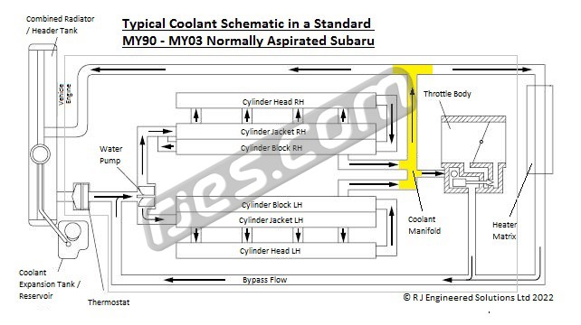
This is the typical coolant system schematic of a standard normally aspirated Subaru engine. It clearly shows how when the thermostat is closed, all of the coolant flow passes through the bypass circuit:
Subaru Engines at Normal Running Temperatures:
Once the coolant has warmed up and the thermostat has opened, its wax capsule is heated by a combination of the flow returning from the heater circuit and the flow returning from the radiator (the two flows combine right where the wax capsule is positioned). The thermostat will remain open under all normal running conditions by varying amounts depending on engine load and ambient temperature, maintaining the intended engine temperature until you turn the engine off.
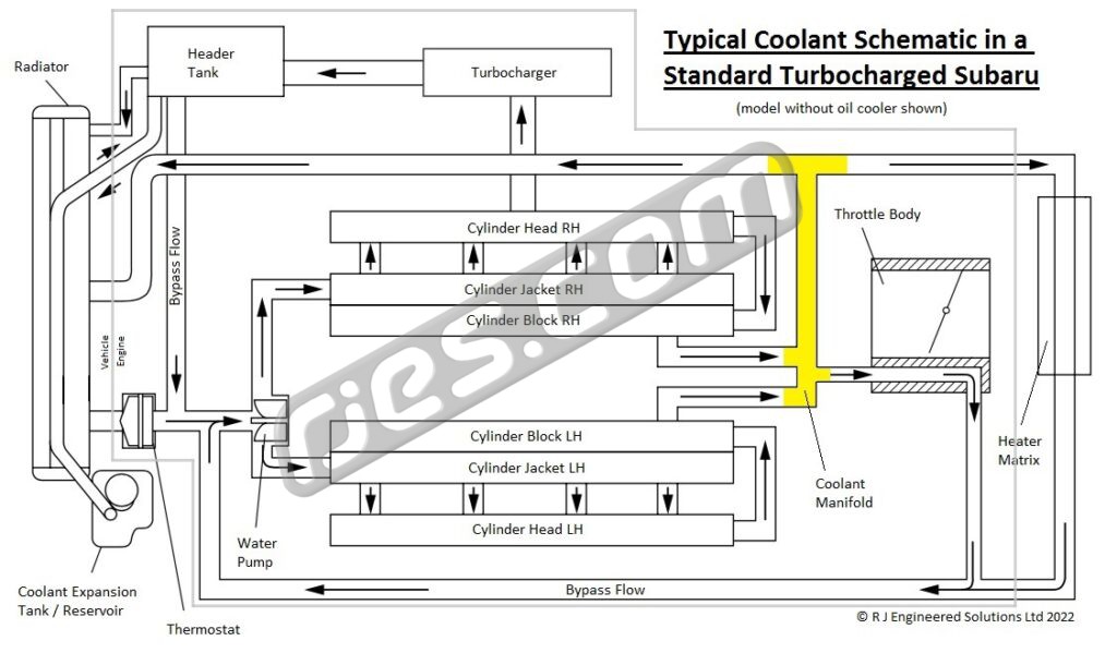
Cooling system differences in the Turbocharged Subarus
The earliest turbocharged Subaru models were the MY90-MY94 Legacy turbo models. Their cooling system was very similar to the normally aspirated models, but with three differences;
1. The turbo models have dedicated header tank mounted on the engine itself, rather than using radiator itself as a header tank. This is required because using the radiator as the header tank, as with the normally aspirated modes, would not position the cap high enough above the turbo, which is mounted unusually high up.
2. All turbos but the MY90 – MY94 Legacy models use water cooler turbochargers, and a additional coolant plumbing to suit.
3. Most of the turbo models also have an oil to coolant heat exchanger, which also requires additional coolant plumbing to suit.
The turbo cooling system effectively works the same as the normally aspirated circuit. Functionally, however, the big difference is to do with the way the additional water cooled systems on the turbos are plumbed. They all increase the amount of bypass flow that the cooling system has, reducing the dependence on hot bypass flow returning from the heater because they all also flow directly onto the thermostat wax capsule. Subaru use a different water pump on the turbo models to achieve this. This means you could probably run a turbo engine without having to add a heater bypass to make VW heaters compatible. This would take some experimenting, but as having a heater bypass makes almost no difference to the heater performance, you may as well use one anyway.
The Cooling System in later Model Subarus:
The biggest change to the cooling system on the EJ series engines was in around MY04. As emissions control became a bigger priority due to tightening emissions legislation, making the engine get up to operating temperature as quickly as possible became a bigger priority, because all the emissions control systems work properly only when everything is up to normal operating temperature. This meant wasting heat warming up a cold heater matrix when the heat isn’t required inside, and a cold automatic transmission fluid cooler was no longer acceptable, as the heat was needed to warm the engine faster.
Starting around MY04 Subaru stopped relying one return flow from the heater matrix to warm the thermostat when the engine is cold by adding dedicated bypass plumbing to warm the thermostat, and a solenoid to the heater circuit, so flow through the heater was prevented unless the heater was turned on. Both of these modifications can incorporated into VW conversions on Subaru engines which have them if required. The solenoid can be wired in parallel with the heater fan. However, some of the changes to the cooling system components on the engines to achieve these modifications make this less straight forward (in particular, the changes to the coolant manifold design and to a lesser extent, additional bypass pipework). In general, unless you need all of the Subaru’s original emissions control systems to be working exactly the way they did in the Subaru, it is far neater and simpler to plumb the engines with this later cooling system as if they were the earlier, simpler type.
Starting around MY05, Subaru added a second thermostat location to many of the EJ series engines, in the coolant manifold. This 2nd thermostat was used exclusively to control the flow of coolant to the gearbox cooler on automatic models, but bizarrely the same manifold design was used on many, but not all manual models too (even though this required a thermostat housing with no thermostat in it, to hold the seal, and a blanking plate), while other manuals still used manifolds much like the earlier designs without a 2nd thermostat location. Subaru EJ series coolant manifolds, and which ones fit which models when reversed is very simple on turbo models from MY90-MY97 and normally aspirated from MY90-MY01, as they all used almost exactly the same part. After these dates, it gets considerably more complex, as that one basic design was replaced with multiple others. Then with these changes in MY05, things got considerably more complex again. See Subaru EJ Series Coolant Manifold Types for more information.
Subaru did not openly document how these later cooling systems work, or even show schematics of how they were plumbed in workshop manuals or easily accessible technical references as they did with the earlier versions. We had to follow the plumbing on a complete Subaru, and monitor which order the various parts got hot in during warm up to verify how they worked.
Coolant Capacity and Cooling System Type
Two of the above points mean that the cooling system in a Subaru powered VW will probably contain a much higher volume of coolant then the Subaru used. This limits the suitability of a closed coolant system for the application, as to be sized correctly for the amount of coolant in the system, the header tank would need to be unusually large, leaving the vented cooling system, as VW used in the water cooled T25 T3 / Vanagon models as the system to use.
VW T25 / T3 / Vanagon Heater and it’s Incompatibility with Subaru Engines
The heater system in most older car designs, including all of the water cooled rear engined VW’s, used a valve which controls the flow of coolant through the heater matrix to control the temperature i.e. fully open = maximum heat, fully closed = no heat. This is fundamentally incompatible with the cooling system on Subaru engines – especially most of the normally aspirated EJ series engines. As can be seen in the schematics shown above in How the Cooling System in a Subaru Works, if you blocked all flow through the heater circuit by fitting this type of heater system and turning the heater(s) off when the engine is cold, not only are you trying to force all bypass flow through the throttle body / idle speed control valve (which is far too small a diameter, so may result in excessive coolant pressure or water pump cavitation), but you’re also preventing sufficient flow getting to the thermostat wax capsule to keep it hot. Therefore it cools, and the thermostat remains closed, regardless of coolant temperature.
Similarly, if you are not fitting a coolant powered heater in your VW engine conversion, but do not understand the Subaru cooling system sufficiently, you could think all that you need to do is block off the heater feed and return pipes on the engine. This cannot work.
To use a heater which uses a coolant flow valve to control temperature, what is needed is an alternative route for the coolant when the heater valve is closed, so the returning coolant always flows over the thermostat wax capsule regardless of heater setting. Theoretically, the best way to do this is to use a diverter valve. This is an active device which splits the flow between the heater matrix the alternative route. Heater 100%, alternative route 0%, and vice versa. These exist, and were the first method we experimented with back in 2003. However, they have a downside too. They are not very practical to install in water cooled T25 / T3 / Vanagon models at all.
Although in theory, a simple heater bypass, which is far easier to install, will compromise the heater performance, testing showed that when the heater bypass design is just right, any performance compromise is not noticeable, with both heaters in a high spec T25 / T3 / Vanagon still performing very well in the coldest UK weather. This has have proven entire trouble free through the next 19 years, but does rely on the heater bypass being designed correctly. Get it wrong, and it either won’t work, or the heater performance will be compromised more than is necessary (there are plenty out there like this – almost always attempts to copy our system be someone who doesn’t understand what they are trying to copy as well as they think they do). The theoretically better diverter valve is absolutely not worth the extra effort, cost and complexity.
With the addition of a suitably designed heater bypass, the heater(s) in a T25 / t3 / Vanagon (or an air cooled VW which has had a heater system fitted in which the heater temperature is controlled with a coolant flow valve), the heater system becomes compatible with the Subaru engines cooling system. A heater bypass is included by default in all of our coolant plumbing kits, as almost all customers do need one, and they double as a convenient joiner between the Subaru and VW plumbing in models which already have heaters.
If you have installed a heater system in which the heater matrix remains hot all the time that the engine is running (i.e. a ‘blended air’ heater, like all Subarus and most other more modern cars use), you so not need a heater bypass. If you specify this when ordering one of our coolant plumbing kits, we can substitute the heater bypass with straight joiners, but it won’t make any noticeable difference if you just use the bypass.
Subaru Powered VW’s in Very Cold Climates
If you regularly have to drive in temperatures below -5 to-10 oC, you can run into a problem where the system described so far can fail. This is a quirk of the unusual reliance on the flow returning from the heater system to warm the thermostat wax capsule on most Subaru engines, and the heaters and or other equipment sometimes connected to it in VW conversions. The easiest way to understand this is to imagine you have an unbelievably large heater matrix in impossibly cold weather. You put the heater on full when the engine is cold, as the engine is warming up. However, all almost the heat energy which flows into the massive heater is dissipated into the vehicle interior, so the coolant flowing out of the heater matrix is always cold. The thermostat can never open, regardless of coolant temperature in the engine, because its wax capsule never sees hot coolant. Therefore the Subaru engine cooling system is sensitive to losing too much heat energy through the heater circuit. It won’t ever happen in a standard Subaru because the heater system is carefully matched to the engine. However, in some applications the heater circuit in a Subaru powered VW can dissipate far more energy than the standard heater in a Subaru, and cause the thermostat to stay closed in very cold weather. The following are what causes the VW heater circuit to dissipate more heat that would be possible in a Subaru:
- Roughly 7m of exposed pipework, outside, between the heater matrix and the engine
- Having a 2nd, rear heater in high spec models, roughly doubles the heat dissipation
- Any less common items which use heat from the heater circuit, such as an LPG evaporator or a Truma type hot water system in a camper
- Obviously, the more of these you have, the higher the ambient temperature you will see the issue beginning at. This was confirmed by a customer with an LPG evaporator, who saw it beginning at around -3 oC.
This issue was solved by Tom Shiels, of www.subaruvanagon.com in Canada, before we started developing our cooling system components. Tom developed a cooling system modification which provides dedicated bypass flow to keep the thermostat wax capsule hot regardless of how much energy is dissipated in the heater – see http://www.subaruvanagon.com/tom/Thermostat%20housingk.htm . We spoke to Tom about his cold climate cooling system modification while developing our cooling system components in the mid 2000’s, and he was unbelievably helpful. He had previously lived in the UK, and was adamant that we don’t see cold enough weather here often enough to need it. We decided not to include it in our cooling system components as standard based on his advice, as the large majority of customers are not using them in Canadian or Scandinavian winter weather. It can relatively easily be added if required though.
Tom’s prediction that his cooling system modification would not be needed in a UK climate proved remarkably accurate – to within probably 2 or 3 oC. When testing during a spell of particularly cold weather here (around -10 oC), in a Syncro with front and rear heaters both on full, we started to see some very strange cooling system behaviour only during warm up. Typically after driving around 3 miles from cold, which is around the point where the engine would normally be reaching normal operating temperature, and the thermostat would be opening, and the temperature would suddenly increase by about 10 – 15 oC. By quickly turning the front heater down, the temperature would stabilise. This was undoubtedly the start of the ‘cold climate issue’. But very rarely gets any colder here, so Tom was correct.
As you’ll see from the link above, Tom’s modification uses a spacer to add an additional port to the thermostat housing / water pump. The same can be achieved extremely neatly using only OEM Subaru parts from other models, and Subaru effectively did the same thing on later models, but I won’t explain how. Support Tom by buying the parts from him if you need them.
Header Tank Caps
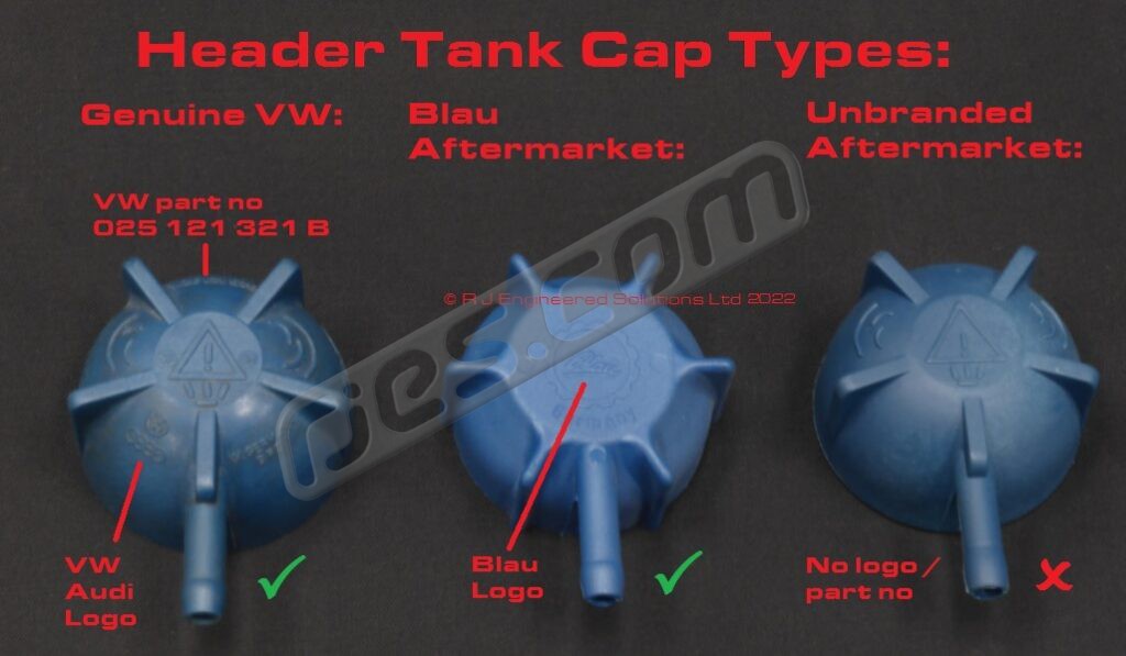
The late model T25 / T3 / Vanagon header tank and expansion bottle system are ideal for use with a Subaru engine conversion, as long as all the components are good quality. This is important, as there is major issue with many of the unbranded aftermarket header tank caps. Note by unbranded, we mean on the cap itself – some of the dodgy caps are sold in boxes printed with the branding by of a very highly regarded aftermarket make, yet the cap inside is unbranded and can be faulty.
Make sure the cap you use is either genuine VW blue cap 025 121 321 B or its Blau aftermarket equivalent. There is a very big problem with a lot of the unbranded aftermarket caps (especially those supplied with a new header tank), and it is often misdiagnosed by those not familiar, often only after having replaced, hoses, radiators and / or heater matrices which have been killed by the misdiagnosed dodgy cap. The good caps are inexpensive – just use one rather than chance it with an unknown cap. The genuine caps say VW Audi on them, and the Blau ones say Blau in the centre:
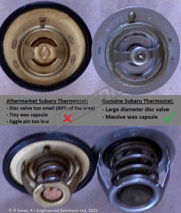
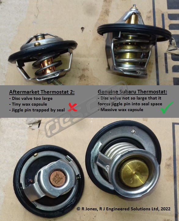
Aftermarket Subaru Thermostats
Very like the dodgy aftermarket VW header tank caps, there are also dodgy Subaru aftermarket thermostats. These can also be sold in the packaging of usually reputable brands, but not perform anything like the correct OEM part. The good Subaru thermostats are not expensive, and the dodgy aftermarket ones sometimes sell for as much, so using them is a false economy. Just use a genuine Subaru part. Subaru thermostats very rarely fail in our experience, and we do not recommend ever replacing them as preventative maintenance, unless you have good reason to, such as you have tested one in boiling water and it either didn’t open or close properly.
How to Identify a Badly Designed Subaru Powered VW Conversion Cooling Circuit
The majority of the cooling system designs published online for Subaru powered VW conversions are not very well designed. Some are not too bad, others are absolutely awful, with the latter giving away more signs that whoever came up with them had a limited understanding of what they were doing. In general it is not as bad now as it was in the mid 2000’s. We first published what we consider to be the optimum circuit design in 2006 or 2007, and quite a few diagrams which others have published since then bear more than a passing resemblance to it. There are still some pretty bad ones out there though. The worst we have seen, which used to be very prominent, really did look like it had had no more thought put into it than ‘what can I join all these pipe ends to so that when I pour coolant in, none of it pours on the floor’. It had certainly had no thought as to how the coolant gets to where it needs to go during filling, or to using the coolant flow to aid separating trapped air from the coolant during filling.
If you want to get an idea of whether a coolant system schematic or plumbing set is any good, check it against the following, and add up its score. The header tank is the tank which is pressurised when the engine is at running temperature if the system has more than one tank:
- Does the coolant flow out of the header tank go to a radiator pipe? (Yes =3, No = 0)
- Excluding any small diameter vent pipes, does the header tank have only one pipe? (Yes =1, No = 0)
- Does the inlet pipe to the header tank (or the only one pipe to the header if there is only one excluding small diameter vent pipes) join the pipe which it is connected to away from its nearest local high spot? (Yes =2, No = 0)
- Does the inlet pipe to the header tank (or the only one pipe to the header if there is only one excluding small diameter vent pipes) join the pipe which it is connected to at the side or bottom, rather than the top? (Yes =1, No = 0)
- Does the cooling circuit add additional breather points which were not there in the Subaru or VW? (Yes =1, No = 0)
- Does the cooling circuit send multiple pipes in directions in the vehicle which are nothing to do with the locations of the key cooling system hardware? (Yes =1, No = 0)
- When constructed as whoever designed it intended, does the cooling circuit feature multiple hose joints which are to do with hose shape rather than hose function, because the hose shapes needed are constructed from multiple generic off the shelf hose bends? (Yes =1, No = 0)
Add up the total score from the above questions for the system you’re looking at. The higher the score, the less thought and cooling system knowledge went into its design. 0 = a well designed system, 10 = a pretty dreadfully designed system.
Reversed Coolant Manifolds
Why use a reversed coolant manifold?
When turning a Subaru EJ series engine around 180o to fit it into the back of a VW, you end up with the coolant outlet to what was the Subaru radiator top hose pointing towards the left hand rear light. In models which originally had water cooled engines, this is pretty much exactly opposite where the coolant pipes are. The coolant flowing out of the top of each half of the crank case on an EJ series engine combines in a bolt on manifold, and the end of this manifold is what the radiator top hose attached to in Subaru’s. The bolt patterns is conveniently rotationally symmetical, however none of the many manifold designs that Subaru used will fit in reverse because the casting fouls on the crankcase.
Various Subaru coolant manifold designs lend themselves to modification to fit in reverse. This involves changing their shape by cutting and welding. If one reversed coolant manifold design suited every application, we would cast new manifolds, however, unfortunately it’s not that simple! Different engines require different reversed manifold specs, especially models with EGR, tumbler valves, turbos, etc.
The advantages of a reversed coolant manifold are:
- Far less length of coolant plumbing
- Less coolant plumbing corners to potentially get airlocked during filling
- Less hoses and hose joins / potential leak points
- Near perfect positioning for the VW coolant pipes in a T25 / T3 / Vanagon
- Done right (some are not), a reversed coolant manifold can make getting the air out of the system during filling considerably easier
- Done right, a reversed coolant manifold van make most of the coolant plumbing in the engine compartment ‘disappear’ – it’s so much neater than any alternative
We either reverse the customer’s own coolant manifold (all customers – not this is not an exchange manifold), or sell reversed coolant manifolds outright (sorry, customers who are abroad only, as sending your manifold can sometimes cost more then the manifold is worth, and we only have limited supplies of manifolds to sell (unless you can put us on to a source of a large quantity of sensibly priced used manifolds of the right type!))
Note 1: The manifold you need to be reversed is not necessarily the one that came on your engine. With most normally aspirated models up to MY03, the manifold which came on the engine will fit when reversed. However some engines with EGR require manifolds from earlier engines to fit when reversed, and MY98 onwards turbo models require specific manifolds from normally aspirated engines to fit when reversed. Also, with turbo engines, the modifications needed to fit the manifold in reverse are not always the same – they depend on the detailed spec of the engine.
Note 2: Not all Subaru coolant manifold types can be reversed. The reversal of your own coolant manifold page shows which manifold types can and cannot be modified to fit in reverse.
Sealing coolant manifolds to used Subaru engine blocks / crank cases
Subaru coolant manifolds are sealed to the crank case halves using o-rings which fit into in grooves in the case halves. The sealing face on the manifold is machined flat. These suffer from crevice corrosion, so when refitting a coolant manifold, to reseal it, as well as using new o-rings there is also often pitting to deal with. Our reversed coolant manifolds come with new o-rings, and their sealing faces are remachined whenever necessary. However, as re-machining the faces and groove to repair any pitting in the crank case halves is not viable, getting them to seal can be difficult unless you know how. If white aluminium oxide is still present the join is unlikely to seal. To get the joint to seal, follow this procedure:
- Clean out all corrosion from the o-ring grooves. If you’ve had to clear out lots of aluminium oxide from the grooves, the chances are that it’ll reveal pitting, and it can be deep
- Once the grooves and any pitting are thoroughly clean, half fill the groove with a sealant such as blue Hylomar
- Push the new o-rings into their grooves
- Coat the top of each o-ring with more blue Hylomar, filling the grooves
- Fit the used manifold with either it’s good original or re-machined faces
Radiator Location – air cooled rear engined VW models (mostly buses)
Excluding the South American market only water cooled T2c models, only one of the air cooled rear engined VW models has an ideal radiator location. Despite only initially being available as air cooled, the T25 / T3 / Vanagon was designed to be water cooled, so it can be converted to the cooling system and water powered heater using almost entirely standard VW parts from a later, water cooled model. There are a few variants of the water cooling / heater system used in the water cooled models, but all are very capable – easily able to cool considerably more powerful engines than VW ever used without modification (as long as they are in good condition).
Every other radiator location apart from at the front involves some sort of compromise.
People have tried fitting radiators in just about every possible location when converting originally air cooled VW models to water cooled. Some of them locations can undoubtedly work OK, but which very few people would be happy with, such as in front of the front panel (i.e. effectively above the bumper), poorly disguised as a spare wheel carrier, or on the roof, poorly disguised as luggage on a roof rack. Others which require major vehicle modification before whether they work or not can be proven, such as behind the rear seat in a Beetle with air ducted in and out via major ducting modification to the windows and body, or large quantities built in the UK with a ridiculously large, unducted radiator between the engine and the rear valance which we have comprehensively proven cannot work without relying on fans far too much.
Each to their own, but almost all customers are looking for something less subtle than that. I.e. they want their VW to still look air cooled, and they want to achieve that in a proven way with minimal modifications to the VW. There are very few locations where both that and correct functioning without relying on fans under normal driving conditions can be achieved. In a Beetle and many of the Beetle based other VW models, the only viable radiator location is in the front, in the spare wheel well, due to the absence of enough space anywhere else where enough air flow is available. In a split screen bus, or a bay window in which the owner doesn’t want to fit the (generally regarded as very ugly) 1.8 Mexican built T2c front mounted radiator system the only suitable location is under the floor.
Two radiators mounted either side of a VW bus engine compartment, and how we determined that this arrangement cannot work:
During our research into where to put the radiator for our bay window or split screen bus cooling system back in around 2006, the original plan was to put one small radiator either side of the engine in the engine compartment, with ducted air from each scoop behind the rear windows. We abandoned this location in favour of under the floor because of the difficulty of providing a header tank location higher than the radiators. The only way to achieve this which would work in all bus models would have been to fit a hatch into one of the ducts from the vent behind a rear window, to access the filler cap from inside the bus., also this location would have required relocation of the battery, or often batteries in campers, which is far from ideal. The only alternative locations would be inside, and all space inside a VW camper is better used for camper related things.
Many years later we got to help a customer to test this system which he’d built and was having trouble with, and the change of location for our system proved to have been the right move. By spending maybe a day helping the customer to work out why the system he had build wasn’t working properly, and what, if anything, could be done to make it work, we gained the results of that testing without having to build anything or spend any money. His system was well built, effectively exactly the same as what we had originally planned to build, and his timing was perfect, as it coincided with about the highest temperatures we ever get in the UK. The results comprehensively proved that the customer’s ‘either side of the engine compartment’ radiator arrangement cannot work satisfactorily. We did get it to cool without relying on fans in the low 30’s degrees C ambient (this is not a high enough ambient temperature for a well designed cooling system), but this required comically large extensions to the inlet duct size, and the engine lid removed, and 100% impractical radiator air exit ducting extending back behind the rear of the body into the low pressure air behind.
One radiator mounted between the engine and the rear valance in a VW bus, and why this arrangement cannot work:
Going back way before we started work on radiator installations for bay and split screen buses, we’d been contacted by many people in the UK who had radiators in this location asking for help as they were not effectively cooling the engine. Their cooling systems would rely on the fans being on at most times -especially when driving at high speed. This is not acceptable, as the purpose of electric fans on any modern engine is to increase cooling when coolant temperatures are higher than they should be – i.e. in abnormal running conditions. With the fan(s) already on trying to achieve cooling under normal conditions, there is no extra cooling in reserve for the abnormal conditions which cause coolant temperatures to rise in any car (e,g towing, very long hills in hot weather, having to slow or stop suddenly on the motorway on a hot day, etc). Under all other circumstances, the natural air flow from vehicle movement will be sufficient to keep the engine cool with a well designed cooling system. Most modern water cooled vehicles have more then one level of additional cooling which can be applied when the coolant temperature is abnormally high. This includes most T25 / T3 / Vanagon models, and all post MY92 Subaru’s, which have at least two.
In a well designed cooling system, the fans should hardly ever come on, and when they do, they should always knock the temperature back down quickly, and therefore turn off again. This should happen in cycles if things get really hot, as the temperature rises, the fan(s) turn on and the temperature reduces repeatedly (the temperature sensors or software controlling the fans intentionally have quite a lot of hysteresis). The fan(s) staying on constantly, as they were doing in these ‘radiator behind the engine’ cooling systems, is proof that the fan system is ineffective – it is either not powerful enough to control the temperature, assuming nothing has gone very wrong with the engine, causing an extreme temperature rise (detonation, running lean, or other causes of likely imminent engine death).
The reason for there being many Subaru powered VW buses in the UK with radiators between the engine and rear valance is that a ‘specialist’ routinely fits them there. They use insanely thick radiator cores, with about the same frontal area as a standard Subaru radiator, apparently oblivious to that fact that the thicker you make a radiator core, the harder it is to get air to flow though it, and by the time any air that does get through to the back of the core, it will no longer be much colder than the coolant). It is no coincidence that the trend in OEM radiator cores has been for them to get thinner and thinner. The ‘specialist’ or their customers also cut holes into the rear valance and / or engine lid (typically hiding the latter by mounting the number plate on stand offs). They also hid colour changing maximum temperature indicators on the engines they install, typically on the bottom of the coolant manifolds. Some of those who got in touch with us looking for a solution said this was apparently an attempt to wriggle out of any (inevitable?) warranty claims for engines damaged by overheating by claiming ‘look, you’ve let the engine get this hot’, as if the customer had a choice when the cooling system is incapable of cooling the engine.
The big problems with this location are:
- There is no room for any ducting on the inlet side of the radiator, as the engine is in the way
- As well as restricting the airflow, the engine and gearbox can only slightly increases the temperature of any air which does make it through the radiator core
- Lack of space for air to exit the radiator, requiring external bodywork modifications
- Lack of engine access. Not too big a deal if the VW is a late bay with an engine hatch, but a big problem if it is a split screen, an early bay / T2a or a type 1 engined late bay / T2b, as they didn’t get the hatches.
See how much effort it took when we helped a customer to get his otherwise well engineered ‘radiator either side of the engine compartment’ cooling system to work. A totally impractical amount of additional ducting both scooping up air behind the rear windows, and venting it through the engine lid hole past the bumper into the low pressure air behind the bus. And that only achieved cooling without the fans being on up to the low 30’s degrees C. A good cooling system design needs to be capable of running insignificantly hotter ambient temps than that before it relies on the fans being on. Similar ducting would be required to get the ‘radiator between the engine and the rear valance’ location to work, except there is no space there for inlet ducting at all in this location.
Additional Water Pumps
A few customers over the years have come up with bizarre cooling systems involving aftermarket electric water pumps, and then got in touch with us for advice when they can’t get them to work correctly. It’s not clear why, but likely that they either imagine or have been told that the Subaru water pump will not be able to pump water all the way to the front of a VW. This is simply not true. The water pump on every Subaru EJ, EZ. EG, etc engine is perfectly capable of pumping the water to the front of a VW reliably for many years.
In fact, we’ve only ever come across one customer have a water pump fail in use in a VW in 18 years, and that failed because a hose blew off due to using one of the dodgy aftermarket VW header tank caps. The pump ran dry, and that kills their ceramic seals very quickly, resulting in coolant leaking from the drain hole in the bottom of the pump (which is there so any coolant leaking isn’t forced through the bearings and into the cam belt housing) when refilling.
Adding ‘solutions looking for problems’ like electric water pumps is both a total waste of your time / effort, and a total waste of money (they’re expensive).
Similarly, our opinion swapping Subaru water pumps as so called ‘preventative maintenance’ is also a false economy, unless you have reason to believe it needs replacing, such as it not turning smoothly. They’re very reliable.
Coolant Plumbing Schematic – Subaru EJ Series Engine in a Rear Engined VW
Coolant Filling and Bleeding Procedure
The following is the procedure we recommend for filling the coolant system on split screen bus, bay window / T2a / T2b, T25 / T3 / Vanagon models converted to Subaru engines. It assumes that the system design exactly follows the design suggested on this site, and every single step is explained here. It looks long, but is actually very simple.
This procedure involves running the engine, so you need to know that your conversion starts up before hand. Do not let it run for more than a few seconds with no coolant in it.
Pre filling checks:
- Coolant type – up to around MY08 Subaru used a very bright (near fluorescent) green coolant which was supplied as a concentrate (to be watered down), known as SUBARU Genuine Coolant or Subaru Long Life Coolant. It had a service interval of 30,000 miles. Part number 000016218, but apparently no longer available. In around MY08 they superseded the green coolant with a blue premixed (50%) coolant called Subaru Super Coolant, which has a service interval of 100,000 miles. The two can be mixed, but if there is even the smallest percentage of the green coolant, the service interval is 30000 miles – the 100000 mile interval only applies when the system is 100% full of the blue coolant.
If you choose to use non genuine Subaru coolant, be prepared to get confused if you start reading up online about which aftermarket coolants are suitable – Subaru don’t publish the spec or a list of suitable products.
Don’t even consider using coolant wich is not based on water – see What do you think of ‘Waterless Coolants?’ for more info - Do not replace a genuine Subaru thermostat unless you have proven that it does not work by testing it (i.e. don’t replace it as so-called ‘preventative maintenance’). If you have a non genuine thermostat, throw it away regardless of brand and whether it works when tested, and replace it with a genuine one.
- If the cap on your coolant header tank is not either a genuine VW blue one (025 121 321 B) or its Blau aftermarket equivalent, throw it away regardless of brand and replace it with the genuine or Blau one. There is a very big problem with a lot of the unbranded aftermarket caps (especially those supplied with a new header tank), and it is often misdiagnosed by those not familiar, often only after having replaced, hoses, radiators and / or heater matrices which have been killed by the misdiagnosed dodgy cap. The good caps are inexpensive – just use one rather than chance it with an unknown cap. The genuine caps say VW Audi on them, and the Blau ones say Blau in the centre. See Header Tank Caps for more details.
- Double check you’ve tightened all the hose clips on all radiator and heater hoses.
Filling procedure:
- Open the heater valve (or valves if you have more than one heater) fully.
- T25 / T3 / Vanagon only – Remove the radiator air bleed screw.
- Remove the pressure cap from the header tank. Do not worry about the expansion tank yet.
- Pour in all the antifreeze first if you are using the concentrate, and watering it down. The coolant system on a Subaru powered T25 / T3 / Vanagon holds about 15 litres of coolant, so work out how much coolant you need dependant on your climate. The antifreeze bottle should provide instructions on this. Then start to add distilled water. Once the header tank is filling up, and the level not dropping, start the engine to get the water pump spinning, and stop it again. The coolant level should drop, allowing you to put more water in.
- Repeat 4, above, until you get any more coolant in. The engine and heater(s) should then be mostly full. The radiator feed pipe is probably part full, and the radiator and radiator return pipe will be pretty much empty.
- Check for leaks, and continue doing throughout the rest of the fill procedure.
- T25 / T3 / Vanagon only – Get a clean bucket and a length of ‘windscreen washer’ sized PVC tube (6.5mm maximum outer diameter). It needs to be about 1.5m long. Trap one end of the tube at the bottom of the distilled water container with something heavy or with a rubber band where ut ebters the bottle neck, and place it on the roof of the bus, at the front. Syphon the water into the bleed hole at the top right of the radiator. It takes a while, so do something else nearby.
- T25 / T3 / Vanagon only – Once the water is overflowing from the radiator bleed hole, refit the bleed screw.
- Bay or split screen bus with our radiator system only – park on a slope front down, or put the back end opn axle stands so the front is lower.
- If the engine installation or temperature gauge arrangement are new, there are a number of recesses on top of the cylinders on Subaru engines, between the ribs on the casting. Put a bit of water in these, preferably one above each cylinder, and keep an eye on them as you let the engine get up to full heat. If any of them boil – it’s too hot. If the installation is not new or and you know the temperature gauge work as it should and reads accurately, or it is one of our temperature gauges, just use the gauge instead.
- Start the engine, this time leaving it running. As soon as it starts, loosen the pressure cap on the header tank, but don’t take it off.
- Our coolant system is designed specifically to encourage air to get out into the header tank as easily as possible. Many other Subaru engine conversion cooling systems seem to have had little to no attention paid to this (many are ‘designed’ by amateurs, who then sell products based around them and promote themselves as specialists despite having no background in automotive engineering and little understanding of what they are doing apart from ‘I see what others are doing and try to copy it’). The coolant level should keep dropping as air bubbles are separated from the coolant in the header tank. Once the tank is partly empty, pour more water in. Do not let the header tank empty fully, or more air will get back into the system. Rev the engine slightly, if necessary, but not excessively. If it does get hot, turn off, let it all cool down, then have another go later.
If the engine is getting hot (it takes a while at idle), you’ll see steam starting to come from the header tank.
DO NOT LET THE COOLANT GET ANYWHERE NEAR BOILING WITH THE CAP OFF – It’s not worth risking burning yourself. - It is very difficult to get the thermostat to open with no load on the engine. Therefore, your heater is likely to get very hot, whilst the radiator is still cold. This is normal. It can seem like the thermostat is not working, but there is almost certainly nothing wrong with it if it is a genuine Subaru part.
- Once you are sure that you can’t get any more coolant in, screw the header tank cap on properly, and shut the engine off.
- Fill the expansion bottle to the maximum mark (use half coolant, half distilled water if not using premixed).
- Take the bus on a short journey. Half a mile is fine if you’re starting with the coolant cold, and the system is mostly full of coolant.
This is critical – you are very unlikely to get the last bit of air out of the system if you miss this step out (no matter how long you try for), and you won’t get the thermostat to open until you do, regardless of coolant temperature.
The load on the engine and the vibration of driving will help encourage the last bits of air out of the system. Taking some extra water and a few tools isn’t a bad idea – very minor problems like hose clips not being tight enough are common on newly installed engines. The coolant level in the header tank should drop while the engine is hot, as more air finds its way out of the system. Then, as the engine cools, it will draw more coolant in from the expansion tank to top up the header tank automatically (they system is self bleeding). Top the expansion bottle up as required. - T25 / T3 / Vanagon only – Once the expansion tank level stops dropping, let the system cool down and undo the bleed screw in the radiator. The radiator is a high spot in the system, so can trap air. If coolant comes out, tighten the screw again – you’ve finished. If nothing comes out, siphon more water into the radiator until it’s full. The heater(s) in the T25 / T3 / Vanagon never trap air despite being high spots and some of them having bleed screws – the flow through them is fast enough to push air out again.
- Keep an eye on the coolant level in both tanks over the first few days of use, and repeat steps 16 and 17 if necessary.
The coolant in a normally aspirated EJ25 powered Syncro runs at 84 degrees C in an ambient temperature of about 16 oC , according to the ECU data. It takes around 2 miles of normal driving on an open road, starting with the engine cold (around 16 oC ) for it to get hot enough to open the thermostat for the first time.
Troubleshooting a Subaru Powered VW Cooling System
If the system that you are working on does not follow the schematics we publish exactly, then you or whoever you got the schematic you’re using knows more about how it behaves than we do. Please don’t get in touch to ask if we can help you to diagnose problems with systems which don’t follow our schematic. We have a very detailed knowledge of how our cooling system designs work. However, there are some truly awful cooling system designs being promoted out there, clearly put together by folk with between little and no understanding of what they are trying to do, and we don’t have the time or interest to experiment with all of them too.